Anatomy of Wear Debris
 This article is the fourth part of a series of “anatomy” lessons within Machinery Lubrication. In this issue, the various modes by which wear debris is created will be examined along with the physical characteristics of each type of wear particle. In addition, microscopic analysis and similar instrumentation will be used to provide an in-depth look at these particles’ unique appearances and how they are formed.
Mechanical equipment deteriorates over time. Depending on the type of work and environmental conditions a machine endures, internal mechanical deterioration can occur in the form of fatigue, rubbing, sliding, abrasion and corrosion. From a macroscopic perspective, the wear debris produced from these deterioration processes may appear as insignificant specks of mass that mostly act and look the same. However, on a microscopic level, this wear debris has a unique morphology (shape and size) and surface topography (roughness, texture and surface pattern) based on the deterioration process or wear mode by which it was produced. If clearly understood, the morphology and topography can offer clues that can be used to prevent imminent machine failure.
| Instrumentation | Analysis Method | Results |
| Spectrometric analysis | High heat vaporization of metals | Parts per million (ppm) of elements |
| Particle counting | Laser light scatter or pore blockage | Number and size of particles |
| Direct image particle counting | Shadow casting from laser | Number and size of particles |
| Ferrous density analysis | Magnetic flux | Number and size analysis of particles |
| Analytical ferrography | Microscopic analysis | Shape, size, texture, color, orientation, etc. |
Wear debris can be defined as particles produced from the breakdown of surfaces within a machine. These particles can range from a submicron size to chunks of metal as large as can be imagined. Wear debris analysis generally focuses on the small, destructive particles, many of which are too small for the human eye to see. These particles may be less than 1 micron to 200 microns in size. If you have particles larger than 200 microns, you probably don’t need anyone to tell you that there is a serious issue within the machine.
Wear Debris Sampling and Analysis
There are many wear debris analysis techniques (see Table 1). Some of these methods can even analyze wear debris right from the oil sample. Analytical ferrography requires wear debris to first be isolated from the collected oil sample. Photomicrograph images of the ferrograms or filtergrams are then studied using an optical microscope. The main advantage of analytical ferrography is its ability to determine particle shapes, sizes and textures as well as identify elements.
Ferrography utilizes either magnetism or membrane filtration to collect particles. ISO standards, such as ISO 16232, ASTM D7670 and D7690, are used to properly prepare these samples and analyze the particles’ visual characteristics. These observed characteristics shed light on where and how these particles were generated.

Ferrograms
As an oil sample flows down a specially designed glass slide called a ferrogram, a magnet is positioned underneath to trap the ferrous particles. The particles tend to collect in strings along the magnetic field. While many of the non-ferrous particles will flow past and not become trapped, some will be held up by gravity or by contact with the trapped ferrous particles. Both bottom and top lighting can be used to help characterize the particles’ critical features.

Filtergrams
In contrast with ferrograms, filtergrams do not have any bias toward ferrous particles. As the oil sample is forced through a filter membrane, any particles greater than the pore size are randomly trapped on the membrane surface. However, bottom light transmission during analysis is poor due to the opaqueness of the filter membrane.
Wear Modes

Rubbing (Break-In) Wear (Abrasive Wear)
As the most common type of wear, rubbing wear occurs whenever there is surface sliding contact within a machine. During initial surface contact, this type of “break-in” wear should be expected. It usually results in a smoother, low-wearing surface. Particles produced from rubbing wear typically have a platelet (two-dimensional) morphology and smooth topography.

Cutting Wear (Abrasive Wear)
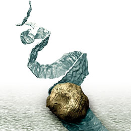
This abnormal wear is produced when two surfaces penetrate one another. As its name suggests, particles are generated from one surface gouging the other surface, creating long, ribbon-like chunks. This wear mode is often compared to machining swarf from a lathe but on a much smaller scale.

Rolling Wear (Surface Fatigue)
Rolling surface contact produces surface fatigue. Particles generated from surface fatigue tend to come in the form of spalls, spherical or laminar particles. The formation of pits and spalls as a result of high load and a low-contact surface area leads to the shaping and sizing of these particles as they are forced out of their original setting. This type of wear typically occurs with components of rolling motion contact, such as in the case of ball bearings.

Rolling and Sliding Wear Combined (Surface Fatigue and Abrasive Wear)
This abnormal combination of wear modes is caused by fatigue and scuffing. It is commonly associated with gear systems, particularly along the pitchline of gear teeth as well as in conditions with too high of a load or speed and excessive heat generation. For example, the surface contact of gear teeth is a combination of rolling and sliding motion. This combined wear mode region, along with the effects of lubricant contaminants, can generate a complex fusion of wear debris.

Severe Sliding Wear
A severe level of wear occurs in excessive loads and high speeds between contacting surfaces. When surface stresses are too great because of increased load and/or speed on the surface contact area, the area becomes unstable and large particles break away, further increasing the wear rate.

Chemical/Corrosive Wear
Corrosive wear is frequently labeled as fretting corrosion, erosion, stress fatigue, etc. These particles are often too small to distinguish individually and are usually the result of improper fluid properties or heavy contamination from water, acid, salt or bacteria. Heat also plays a major role in corrosion. Most lubricants have rust/corrosion-inhibiting additives to combat the effects of chemical wear.
Particle Morphology and Topography
Since wear particles detach from internal machine surfaces in a variable manner, their morphology and topography are unique. However, they also fit certain patterns based on the actions by which they become detached.

Platelet-shaped Particles
These two-dimensional particles are generally flat with a rough perimeter. Their thickness typically is about one-tenth to one-thirtieth their lateral dimension. They can be further described as having either a laminar or wedge shape. One of the most common ways platelet-shaped particles can occur is by normal and tangential forces through contacting asperities.

Spherical Particles
As their name implies, these particles are fundamentally spherical. Normally less than 10 microns, they appear in small numbers and are sometimes fused together. As wear debris, spherical particles have been associated with rolling-element bearings and are often a precursor to fatigue failure. It must be noted that spherical particles are frequently found as contaminants rather than as wear debris. This type of spherical-shaped contaminant likely will be larger than 10 microns and often is a byproduct of welding and grinding processes.

Wire or Curl-shaped Particles
Typically long and skinny, these particles may resemble a wire, splinter or ribbon shape. While they can have smooth sides and edges, they normally will have a rougher appearance. Another common characteristic is how they are curled, which is similar to a shaving curl in a wood-planing process. For this reason, the particle may be rough on one side and smooth on the other. These types of particles have been linked to cutting wear where one of the contacting surfaces possesses an asperity or lodged particle that is plastically rigid compared to the other surface from which the ribbon-shaped particle is gouged out.

Chunks or Irregular Particles
The adhesion theory offers a possible explanation for why particles produce irregular shapes. During surface adhesion, the asperities of two contacting surfaces flatten each other, creating a fracture on one of the surfaces. The surface interaction transfers fragment material, which adheres to the opposing surface. This can result in the formation of particles that have unusual shapes and are a mixture of elements. The shapes often are difficult to define, as several wear modes may be at work concurrently within the system. As these wear particles act as abrasive contaminants between continually contacting surfaces, they transform into unusual shapes.

Non-Ferrous Corrosion Particles
Corrosion particles typically are extremely small (submicron). Magnetic collection techniques can be effective in gathering these particles, which are too small to view in individual detail.


Ferrous Oxide Particles
Oxide particles, which are either red or black iron oxides, are produced from chemical reactions between iron and oxygen. Red oxides are an indication of moisture in the system, while black oxides indicate inadequate lubrication and excessive heat generation in the system.
Other Particles
The particles described previously comprise only those generated from wear-induced causes, but a mechanical system can contain an assortment of other particles from environmental contaminants like water, dust, etc., to human-agency contaminants such as machining byproducts. Even some lubricant additives can be mistaken for wear particles during wear debris analysis. Nevertheless, wear debris analysis is quite useful for discovering which degrading actions are occurring within a machine or how a machine failed.
This illustration shows how the various types of wear particles are associated with the different wear modes.
Although analysis techniques such as observations from precise heat treatments or adding specific chemicals can help in determining the elemental composition of particles, spectrometric analysis is generally more effective in providing the elemental composition of contaminants within an oil sample. Analytical ferrography remains the best technique for determining the morphology and topography of wear debris, which is essential in identifying the root cause of the particles.

Standards Relating to Wear Debris Analysis and Particle Characterization
ISO 16232 7/8: Road Vehicles – Cleanliness of Components of Fluid Circuits
Parts 7 and 8 of this ISO standard focus on the methods for determining the size distribution of particulate contaminants and for characterizing their shape and physical profile, especially those from automotive components. The technique can be applied to lubricants from most all machines that follow the same principle of incurring wear or ingression of particles into the lubricated area of the components. The particles are analyzed microscopically using computer image analysis.
With proper method extraction managed, this ISO standard also specifies a method for particle sizing and counting by use of microscopic analysis as well as an established system for expressing the results.
For more information regarding these standards, visit the International Organization for Standardization website at www.iso.org.
ASTM D7684, D7670 and D7690: Microscopic Characterization of Particles from In-Service Lubricants (by Analytical Ferrography)
These new ASTM standards specify methods for proper classification and reporting of results for in-service lubricants containing particulate debris either from wear, ingression or elsewhere. Included in the standard guide is suggested terminology for reporting, logical framework and possible root causes. The primary method for analysis within these standards is through ferrography, either by use of linear or rotary glass slides, in addition to guides for filter debris analysis and magnetic plug inspection, among other methods. For more information regarding these standards, visit the ASTM website at www.astm.org.
References
Anderson, Dan P. (2012). Wear Debris Atlas. Jim C. Fitch (Technical Editor). Tulsa, OK: Noria Corporation.
Rigney, David A. (1981). Fundamentals of Friction and Wear of Materials. Metals Park, OH: American Society for Metals.
Thibault, Ray. (2006, Nov.-Dec.). “Improving Predictive Maintenance Through Wear Debris Analysis.” Lubrication & Fluid Power.