How to Prevent Foaming and Air Dispersions in Industrial Gear Oils
Lubricating oils are not completely free of air. Whether during operation or storage in barrels, oils are constantly in an exchange process with their air-containing environment. Even if the oil is free of air bubbles, it will have a proportion of dissolved air. This depends primarily on the gas solubility, but pressure and temperature also have an effect. Some mineral oils can have air content approaching 9 to 11 percent volume at atmospheric pressure and room temperature. As long as the air remains dissolved in the oil, this generally is not a problem.
However, free air bubbles, which usually are caused by constantly immersing machine parts or through oil returning to the reservoir, can lead to serious disruptions in equipment operation, including impaired cooling effect, increased oxidation tendency, shortened oil life, reduced carrying capacity of the lubricant film, oil spills, decreased oil pump capacity, lack of lubrication, cavitation and microdieseling.
| Dissolved Air | Undisolved Air |
|---|---|
| Dissolved into molecule structure (mineral-based oils = approximately 9%) | Not dissolved into molecule structure |
| No “free” air; no bubbles present | “Free” air; air bubbles present (entrained bubbles in the body of the oil or on the oil’s surface, i.e., foam) |
| Causes | |
| Permanent reaction with air from environment by diffusion; air content primarily depends on pressure and temperature | Generated primarily by entrainment of air bubbles, e.g., by immersing machine parts, return of the oil into the reservoir, suction of air bubbles, etc. |
| Consequences | |
| No problems | Problems |
| Variations of pressure and temperature can “transform” dissolved air into free air bubbles | Greatly increased compressibility, affected lubrication and cooling capabilities, increased oil oxidation, cavitation, microdieseling, etc. |
Foam and Air Release
Oil returning to a reservoir has enough time to separate air in the form of air bubbles. The main influences on the speed at which these air bubbles separate from the oil and rise include the size of the bubbles, the oil’s viscosity and the oil temperature. The amount of dispersing additives, the oil’s density and any impurities also play a role.
As air bubbles arrive at the surface, surface foam is formed. Therefore, foam consists of a series of air bubbles, which are each surrounded by a skin of oil. As a function of the oil’s surface tension, this skin of oil can burst more or less rapidly. The time it takes for the ascended bubbles to burst and achieve complete separation from the oil is mostly dependent on the oil’s viscosity and temperature, but the content of polar aging products, impurities and certain additives also have a bearing. The oil property that describes how fast these ascended bubbles burst is called the foaming behavior.
As seen in Table 2, air release cannot be improved by additives. However, the foaming behavior of lubricating oils can be improved by anti-foam additives, which reduce the surface tension of the oil, i.e., by the well-proportioned addition of silicone-containing compounds or oil-soluble polyglycols. Too many anti-foam additives can lead to a significant deterioration of the air-release capability.
| Air Release | Foaming Behaviour |
|---|---|
| At what speed do air bubbles rise to the surface? | At what speed do ascended bubbles burst? |
| Residence time in the tank should be higher than the air release to avoid re-intake of air bubbles. | Ascended bubbles should burst fast to avoid a stable or increasing foam buildup. |
| Large bubbles ascend faster than small bubbles. | Small bubbles produce big bubbles before bursting. |
| In higher viscosity oil, air bubbles rise less quickly. | Higher viscosity oils show higher foam stability. |
| Air release cannot be improved by additives. | Foaming behavior can be improved by additives. |
| Aspiration of air bubbles promotes pseudo cavitations; dieseling effect reduces the capacity. | Surface foam reduces cooling capacity and promotes oil oxidation. |
| An air-oil emulsion distributed over the entire volume of oil leads to serious problems in plain bearings or hydraulic systems, including diminished capacity, limited lubrication and cooling, declining oil life, cavitation, microdieseling, etc. | |
| ISO VG/Type | 32 | 46 | 68 | 100 | (150) | (>320) |
| Turbine Oil DIN 51515, ISO 8068 | 5 | 5 | 6 | — | — | — |
| Hydraulic Fluid (HLP/HM) DIN 51524/2, ISO 11158 | 5 | 10 | 13 | 21 | 32 | — |
| Lube Oil (CLP/CKC) DIN 51517/3, ISO 12925/1 | — | — | — | — | — | — |
| ISO VG/Type | 32 | 46 | 68 | 100 | (150) | (>320) | |
|---|---|---|---|---|---|---|---|
| Turbine Oil | I | 450/0 | — | — | |||
| DIN 51515, | II | 50/0 | — | — | |||
| ISO 8068 | III | 450/0 | — | — | |||
| Hydraulic Fluid (HLP/ HM) | I | 150/0 | — | ||||
| DIN 51524/2, | II | 75/0 | — | ||||
| ISO 11158 | III | 150/0 | — | ||||
| Industrial Gear Oil (CLP/ CKC) | I | 100/0 (100/10) | — | ||||
| DIN 51517/3, | II | 100/0 (100/10) | — | ||||
| ISO 12925/1 | III | 100/0 (100/10) | — | ||||
Operational Causes
The possible causes of foam formation in gears can be divided into two groups: transmission and lubricating oil. If lubricating oil mixes with other lubricants or contaminants such as dust or water, foaming can result along with oil aging, which leads to the formation of polar oil-aging products, an increase in viscosity or filtering out of anti-foam additives by bypass filters.
Transmissions with short residence times of the oil in the reservoir are particularly sensitive to changes. Increased air entry due to a high oil level may cause high flow velocities of oil injection directly into the gear teeth.
In practice, you often see an overlap of several of these factors. While each factor on its own would not be a problem, a combination of these factors can lead to increased foaming. This makes it difficult to identify the actual causes.
Air Release Standards
Several standards exist for the measurement of air-release properties: ASTM D3427, ISO 9120 and IP 313. All of these use the same test procedure (the impinger method). Air is blown into the oil sample through a valve at a precise time and pressure. The release of dispersed air bubbles is recorded until the volume remains unchanged. The air release is defined as the number of minutes needed to release the air dispersed in the oil to 0.2 percent volume.
Air release is an important property for many applications. For example, minimum air-release requirements are included in the standards for new hydraulic fluids and turbine oils. Modern turbine oils and hydraulic fluids often have lower air-release values than the minimum requirements listed in Table 3. Air release is also a key property for the condition monitoring of in-service fluids. For highly viscous lubricating oils, air release is measured at higher temperatures, e.g., 75 degrees C.
Foaming Standards
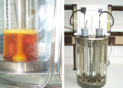 The measurement of the foaming characteristics of lubricating oil is standardized in ASTM D892 (ISO 6247 and IP 146). Air is pumped into the oil through a spherical, porous stone. Small air bubbles are created, which form an air-in-oil dispersion. These air bubbles rise to the surface where a layer of foam builds up. After five minutes, the air flow is stopped. The volume of foam is measured immediately after switching off the air and after 10 minutes.
After the first test sequence at 24 degrees C, a second oil sample is measured in the same way but at 93.5 degrees C and then at 24 degrees C. The test result for each sequence consists of two numbers, as seen in Table 4. However, DIN 51517/3 includes a footnote that seems to discredit ASTM D892 as a test procedure for foaming characteristics of industrial gear oils:
“A change of the given test procedure for the foaming characteristics will be done if a new or modified test procedure is standardized.”
Certainly the test equipment does not work as well with highly viscous oils in comparison to turbine oils or hydraulic fluids. One of the reasons could be because the amount of air pumped into the oil depends on the viscosity. Highly viscous oils generate a high counter-pressure. The higher the viscosity, the lower the amount of entrained air and foaming characteristics. Air entrainment in a gearbox also functions differently than in a hydraulic system.
Flender Foam Test
The measurement of foaming characteristics according to Flender is standardized in ISO/DIS 12152. Inside the Flender foam test rig, a horizontal pair of spur gears rotates at 1,405 revolutions per minute. Lubricant is filled into the apparatus until the spur gears are covered halfway up the side. The gears start to turn for five minutes and splash air in the oil like a mixer.
After 90 minutes, any change in the oil phase, oil dispersion and foam volume are documented. The percentage increase in the oil volume one minute after stopping the instrument as well as the percentage increase in the volume of the air-oil dispersion five minutes after stopping the instrument are two important values in evaluating and assessing the test.
For the percentage increase in the oil volume one minute after stopping the instrument, the following rating should be used:
The upper limit of more than a 15-percent increase in the oil volume one minute after stopping the instrument does not equate to an actual foaming limit for existing gearboxes. This limit is only valid for the test instrument and the standardized test procedure. It is based on the experiences of Siemens (Flender) in meeting the requirements of Flender gearboxes.
The percentage increase in the volume of the air-oil dispersion five minutes after stopping the instrument is limited to a maximum of 10 percent. This limit is required by leading manufacturers of oil pumps to avoid cavitation.
Case Study #1: Lifting Gearbox
Excessive foaming in an industrial gearbox containing 1,000 liters of gear oil was observed during operation. Contamination or mixing of different oils or other fluids is the most common cause. Therefore, a sample of the new oil was requested. One sample was taken from the middle of the oil reservoir and another from the foam. The results are shown in Table 5.
| 1702513 | 1702514 | 1702515 | |
|---|---|---|---|
| Foam | Reservoir | New Oil | |
| Water (Wt.-%) | <0.1 | <0.1 | <0.1 |
| Silicon (ppm) | 6 | 2 | 0 |
| Kin. Viscosity (40°C, mm2/s) | 145.3 | 115.2 | 104.0 |
| Kin. Viscosity (100°C, mm2/s) | 15.27 | 12.3 | 11.1 |
| Viscosity Index (VI) | 107 | 97 | 91 |
| Calcium (ppm) | 174 | 55 | 0 |
| Phosphorus (ppm) | 189 | 73 | 25 |
| Zinc (ppm) | 106 | 34 | 0 |
| Barium (ppm) | 1 | 0 | 0 |
| Sulfur (ppm) | 3,588 | 3,605 | 3,481 |
| Acid Number (mgKOH/g) | 0.25 | 0.18 | 0.19 |
Elemental analysis revealed the cause of the excessive foaming - the oil was contaminated by another fluid. The analysis also showed differences in additive elements of the new oil, the foam and the sample from the gearbox’s oil reservoir.
Case Study #2: New Oil After Filling a Gearbox
When new oil was used to fill a gearbox and the gearbox was started, the oil showed an increased foaming tendency. The customer believed the cause of the increased foaming tendency was the removal of anti-foaming agents due to bypass filtration. To obtain more information, oil samples from the new oil and from the oil in the gearbox were analyzed (Table 6).
| 8031962 | 8021706 | |
|---|---|---|
| Gearbox | New Oil | |
| Water (Wt.-%) | <0.1 | <0.1 |
| Silicon (ppm) | 0 | 9 |
| Kin. Viscosity (40°C, mm2/s) | 330.9 | 330.8 |
| Kin. Viscosity (100°C, mm2/s) | 37.4 | 38.2 |
| Viscosity Index (VI) | 162 | 166 |
| Boron (ppm) | 31 | 33 |
| Phosphorus (ppm) | 371 | 414 |
| Zinc (ppm) | 0 | 0 |
| Barium (ppm) | 0 | 0 |
| Sulfur (ppm) | 4,932 | 5,013 |
| Foam S1 (ml/ml) | 110/10 | 110/0 |
| 8021708 | 8021706 | |
|---|---|---|
| Filtered Oil | New Oil | |
| Water (Wt.-%) | <0.1 | <0.1 |
| Silicon (ppm) | 2 | 9 |
| Kin. Viscosity (40°C, mm2/s) | 330.1 | 330.8 |
| Kin. Viscosity (100°C, mm2/s) | 38.1 | 38.2 |
| Viscosity Index (VI) | 167 | 166 |
| Boron (ppm) | 31 | 33 |
| Phosphorus (ppm) | 422 | 414 |
| Zinc (ppm) | 0 | 0 |
| Barium (ppm) | 0 | 0 |
| Sulfur (ppm) | 4,938 | 5,013 |
| Foam S1 (ml/ml) | 10/10 | 10/0 |
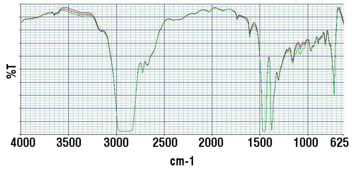
The results showed the silicon-based anti-foaming agent had been completely removed. There were also small changes in additive content. An infrared spectrum of the gearbox sample in comparison to the fresh oil can be seen in Figure 3.
The spectrum revealed cross-contamination by another fluid. A fresh oil volume was then filtered to determine if bypass filtration was the only reason for the foaming or if cross-contamination also had an effect. After filtration, a sample was taken and analyzed (see Table 7).
The analysis showed that the anti-foaming agent was not completely removed. A small amount (2 parts per million) remained. Although the slight changes in the amount of anti-foaming agent are not visible in the infrared spectrum (Figure 4), a good correlation of the sample before and after filtration is evident.
Some filter manufacturers have even included the Flender foam test in their testing procedures to avoid problems with removed anti-foam agents.
Case Study #3: Main Gearbox of a Wind Turbine
A wind turbine’s main gearbox was initially filled with a mineral oil. After operating for 25,000 hours, the oil was changed, and a switch was made to a synthetic polyalphaolefin-based oil. The new filling started to foam almost immediately. Oil analysis was utilized to determine whether the gearbox was flushed properly (see Table 8).
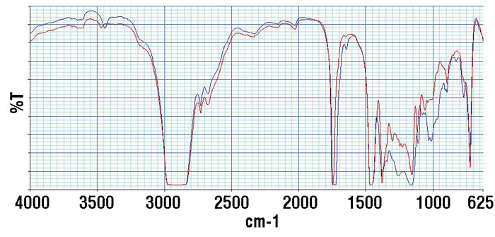
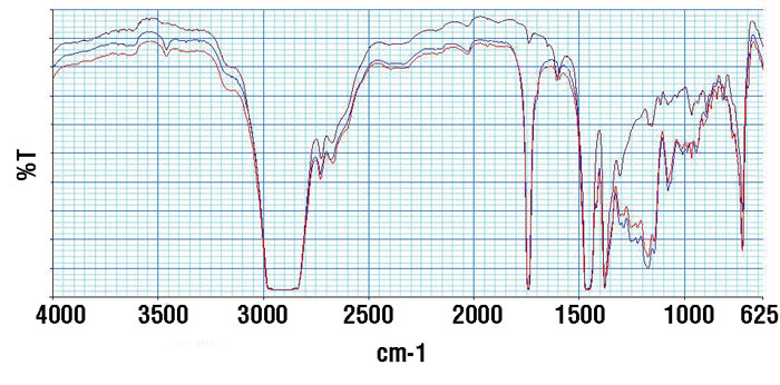
Small changes in the element concentrations were visible. The infrared spectrum (Figure 5) shows the contamination more clearly. The brown graph represents the spectrum of the old oil, while the blue graph is the new oil, and the red graph is the oil from the gearbox after the oil change.
Case Study #4: Cement Mill Gearboxes
During a scheduled downtime, the oil in two industrial gearboxes was changed. Due to the positive experiences with the oil, the same oil type was used again. After the oil change in both gearboxes, increased foaming was observed. The gearboxes were stopped again, and the customer complained to the oil manufacturer about the “bad oil quality.” The oil manufacturer took samples from the foaming oil in both gearboxes and from the new oil that was delivered (see Table 9).
| 2295772 | 1504280 | 2155316 | |
|---|---|---|---|
| After Oil Change | New Oil | Old Oil | |
| Water (Wt.-%) | <0.1 | <0.1 | <0.1 |
| Silicon (ppm) | 16 | 25 | 0 |
| Kin. Viscosity (40°C, mm2/s) | 332.3 | 325.1 | 318.8 |
| Kin. Viscosity (40°C, mm2/s) | 36.7 | 36.5 | 23.4 |
| Viscosity Index (VI) | 157 | 160 | 92 |
| Calcium (ppm) | 0 | 0 | 0 |
| Phosphorus (ppm) | 393 | 432 | 197 |
| Zinc (ppm) | 3 | 0 | 22 |
| Barium (ppm) | 0 | 0 | 0 |
| Sulfur (ppm) | 3,992 | 3,857 | 10,690 |
| Acid Number (mgKOH/g) | 0.94 | 0.99 | 0.82 |
| Flender Foam (%) | 18 | - | - |
| 702513 | 1702514 | 1702515 | |
|---|---|---|---|
| Gearbox A | Gearbox B | New Oil | |
| Oil Usage (hours) | 500 | 210 | 0 |
| Water (Wt.-%) | <0.1 | <0.1 | <0.1 |
| Silicon (ppm) | 4 | 2 | 3 |
| Kin. Viscosity (40°C, mm2/s) | 204.3 | 200.7 | 216.1 |
| Kin. Viscosity (40°C, mm2/s) | 18.8 | 18.6 | 18.97 |
| Viscosity Index (VI) | 101 | 103 | 98 |
| IR-Oxidation (A/cm) | 7 | 11 | - |
| Calcium (ppm) | 15 | 18 | 18 |
| Phosphorus (ppm) | 175 | 163 | 156 |
| Zinc (ppm) | 5 | 6 | 7 |
| Molybdenum (ppm) | 859 | 861 | 852 |
| Sulfur (ppm) | 10,752 | 10,768 | 10,690 |
| Acid Number (mgKOH/g) | 0.83 | 0.79 | 0.85 |
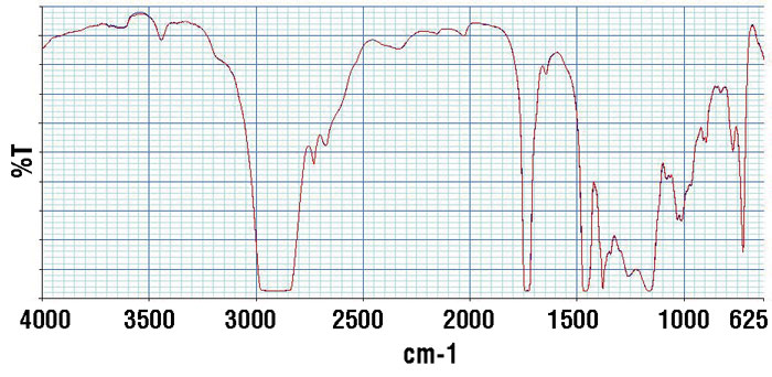
The elemental analysis results were not unexpected. Only the viscosity of both gearbox samples was slightly decreased. This decrease was within the limits for ISO VG 220. However, in comparison to the fresh oil sample from the same batch, it was noticeable. The infrared-oxidation value was also abnormal and much too high for this limited usage. The infrared spectrum indicated contamination with an ester-containing fluid (see Figure 6).
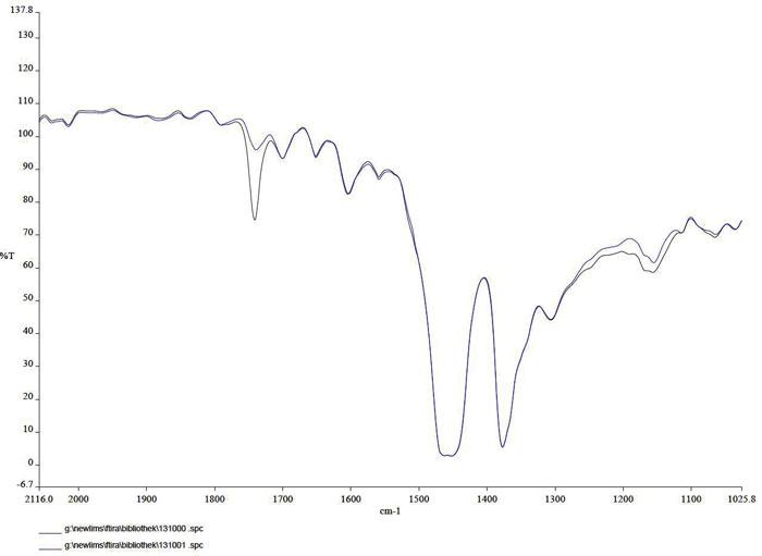
While discussing the results, the customer revealed that a cleaner had been used. The cleaner contained ester-based components, and its viscosity was very low. It became obvious that the cleaner was the reason for the increased foaming.
In conclusion, the formation of foam or finely dispersed air bubbles is one of the most frequently discussed phenomena in the operation of gearboxes. Excessive foaming can lead to serious operational problems as well as safety and environmental hazards.
Different standardized test procedures are available to estimate the air release and foaming properties of lubricating oils. However, the common test methods for air release (ISO 9120, ASTM D3427-12 and IP 313) and foaming properties (ASTM D892, ISO 6247 and IP 146) do not provide reliable information for industrial gear oils. Therefore, a special test (Flender foam test, ISO 12152) has been developed and standardized. This test delivers much more reliable results and can improve the reliability of gear oils. The examples given in this article demonstrate the application of these test procedures and offer an overview of a variety of foaming problems as well as their causes.
About the Author
By Rudiger Krethe, OilDoc.
