Ask the Experts
How Filtration Affects Oil Analysis
"A recent article suggested that particles that are removed from oil reduce failure detection via oil analysis. I use an oil centrifuge on my personal Cummins engine installed in a pickup, and I use oil analysis at oil change intervals. What would happen if I sent the residue to a lab to be analyzed after cleaning the 'stuff' out?"
 It’s true that particles that are removed from oil will reduce the effectiveness of oil analysis to detect failure. Oil analysis cannot detect particles that aren’t there. Nevertheless, most particles that are removed by oil filters and centrifugal separators (or centrifuges) are too large to be seen by many oil analysis instruments such as spectrometers. Spectrometers are biased toward smaller particles in the range of 3 microns or less. This is much smaller than the majority of particles trapped by these filters or centrifuges, which typically are around 10 microns or larger. Therefore, the smaller (and just as significant) particles remain in the oil for analysis.
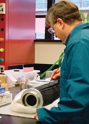
However, larger particles that are trapped by filters or centrifuges are important as well and can be more closely associated with advanced wear. Filter debris analysis provides one possible method for this type of analysis. Several larger commercial laboratories offer this service where a swatch of contaminant-filled filter media can be analyzed.
If a centrifuge is used in the engine, the sediment inside can be gouged out and sent to the lab along with simple instructions for how it should be analyzed and information regarding its source. The best spectrometer in this case would be an X-ray fluorescence (XRF) spectrometer, which is available at many larger commercial labs.
Alternatively, the laboratory could use a solvent to break down the gouged sediment from the centrifuge and then transfer it through a membrane. This would trap the large particles on the surface of the membrane, which could then be analyzed through microscopic analysis or analytical ferrography.
Of course, the majority of sediment and residue found within the centrifuge will be soot or sludge deposits and thus will lack vital oil properties such as dispersancy to be analyzed within the engine oil. This is important to understand because filter/centrifuge debris will be limited to the characteristics of the contaminants, while oil analysis can provide information on the overall characteristics of the oil. Therefore, it is necessary to analyze the oil as well as gather information on the concentration of oil additives and any changes to the base oil.
Filtration is essential and should not be curbed for the sake of oil analysis. Failure detection via oil analysis is multifaceted. Particles trapped by filtration are only a slice of this process. Continuing to carry out oil analysis in cooperation with filter debris analysis may be the ideal solution for achieving effective analysis while maintaining your motor oil's filtration.
3 Ways to Detect Cavitation Wear in Hydraulic Systems
"We think cavitation wear may be occurring in our hydraulic system but don't know for sure. Is there a way to determine this?"
 Cavitation can be determined by three easy means of detection: abnormal noise, high fluid temperature and slow operation.
Abnormal noise can be caused by two sources: aeration and cavitation. Aeration is the more alarming of the two. Sometimes referred to as “hammering,” it occurs when air is entrained in the system. Large air bubbles compress and decompress, resulting in a "banging" noise. In severe cases, this can lead to the failure of piping and equipment. It may also be confirmed by foaming and erratic operation of actuators.
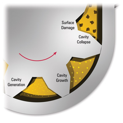
In the case of cavitation, the absolute pressure falls below the vapor pressure of the fluid, creating vapor cavities. These cavities will implode, which produces a knocking sound. This can be identified with vibration sensors or acoustical analysis equipment. At times, this may even be loud enough to be heard. The source of this noise is actually the implosion and subsequent micro-jet impinging on the surfaces of the system. Imagine a very small water jet cutting on the system surfaces. This constant impingement sounds similar to a growling or rattling in the system.
High fluid temperature is the result of the compression of air and other entrained gases in the fluid, or when the fluid moves from a high-pressure to low-pressure area without performing useful work. This takes place when the fluid leaks past internal seals in a piston/cylinder arrangement or when there is an improperly adjusted relief valve.
If the heat is not dissipated, it can have an effect on the viscosity of the fluid, which impacts the lubrication of the system and components as well as causes other problems that increase the likelihood of further cavitation. Research has shown that the higher the viscosity, the lesser the impact and likelihood of cavitation. The inverse of this is also true; as the viscosity decreases, the likelihood of damage from cavitation increases.
Slow operation and longer cycle times are usually the first indication that there is a problem. Remember that the operation of the system is based on flow. If there is a loss of speed in your actuators, there is likely a loss of flow somewhere in the system. This is generally caused by leakage, such as from a ruptured hose, blown seals, leaking fittings, etc. These are fairly obvious and easy to correct.
Internal leakage is much more difficult to identify but not impossible. When fluid moves from a high-pressure to low-pressure zone without doing work, heat is generated. This can be determined with infrared thermometers, sometimes in conjunction with flow meters.
In short, noise, temperature and cycle times are good indicators of cavitation in your hydraulic systems. As with everything else, early detection is the best way to prevent equipment failure and subsequent downtime. Be proactive and look for these indicators. Failure to do so can have a huge impact on the bottom line.
