A Practical Approach for Evaluating Oil Analysis Results with Limit Values
The evaluation of oil or grease analysis results is often a tough job for a diagnostician, demanding experience in mechanical engineering and chemistry. However, modern tools and statistical methodologies can support and improve the process. The first step is to define a proper set of test methods that delivers sufficient parameters for answering important questions about the sample while still being as economical as possible.
After determining the test parameters, the next challenge is to set up limit values and guidelines for the evaluation. In some cases, general limit values are available. However, in many cases, oil, component or equipment manufacturers cannot or will not supply complete limit sets. So how can a meaningful diagnosis be created? One way is with the help of an experienced engineer who knows the application and when critical values are exceeded. It is also easier if previous samples exist. Developing parameters over a period of time can identify layers or single parameters that move away from the regular trend line. Absolute limit values must also be applied in order to have a fixed reference point for the critical region.
An adequate set of oil analysis results from the same or comparable equipment/application is the baseline for statistical methods. ASTM D-7720 describes an approach for identifying alarm limits by statistical methods, but a large set of data and statistical guidelines do not automatically provide proper limit values. The quality of the data set can have a significant impact on the statistical results. It may make the difference between having reasonable statistically based limits or nonsense.
This article will show how carefully filtered data sets within a sophisticated structure can deliver valuable limit values. The system, which is based on an application matrix, enables oil samples to be categorized with as much detail as the sample information allows. Combined with an advanced evaluation program, this is the basis for defining limit values, applying them with evaluation guidelines and proving them on a regular basis.
Analyzing an Oil Sample
The analysis of a used oil sample produces a lot of data. A typical lab report contains in the range of 20 to 40 single measurement results. In order to provide a proper diagnosis or trigger the necessary actions based on the analysis, typical or normal ranges for each element must be known. The oil type, construction, maintenance and operating conditions are the four main influencing factors for evaluating an oil sample.
A single rating for each oil analysis parameter does not cover the complexity and interdisciplinary knowledge in the fields of mechanical engineering, chemistry, tribology and lubrication that must be applied. If an evaluation is based on one element that has exceeded a limit, incorrect interpretations are possible. Some labs offer a comment for every oil sample, pointing out critical areas of the analysis along with recommendations for the next maintenance action. However, lab reports generally do not contain limit information in order to avoid misinterpretation by the end user.
Limit Values
Most oil analysis reports from commercial laboratories contain a rating based on the traffic-light principle. This utilizes a three-stage color code (green, yellow and red) to quickly indicate the severity of a sample result. If a large number of samples must be handled, it may make sense to filter the yellow- and red-flagged samples in order to decide what kind of maintenance action is necessary. Green-flagged samples can be stored for trending and documentation.
| Test Method | Limit Values | |
| Viscosity at 100°C (mm2/s) | ASTM D445 | Max. 17.5 |
| DIN 51562 | Min. 11.5 | |
| Base number (mg KOH/g) | ASTM D2896 ISO 3771 | Min. 3 and BN >AN |
| Acid number (mg KOH/g) | ASTM D664 | New oil value +2.5 |
| ipH value | Min. 4.5 | |
| Water (% by volume) | ASTM D6304 EN 12937 | Max. 0.2 |
| ISO 6296 | ||
| Glycol (mg/kg) | ASTM D2982 | Max. 100 |
| Oxidation (A/cm) | DIN 51453 | Max. 20 |
| Nitration (A/cm) | IR method | Max 20 |
| Wear elements (mg/kg) | RFA | ICP |
| Iron | Max. 30 | |
| Lead | Max. 20 | |
| Aluminum | Max. 10 | |
| Copper | Max. 20 | |
| Tin | Max. 5 | |
| Silicon | Max. 15 |
The coding system should not be too complicated. Otherwise, it loses its advantage of providing quick and simple decision guidance. At the same time, it must be reasonable and consistent for comparable oil analysis patterns. Proper limit parameter sets that can be both absolute or trend-based are the basis of this consistency.
Standardized processes for the creation and revision of limit values combined with well-founded guidelines for the recognition of failure modes and the identification of normal conditions are fundamental for a high-quality oil analysis program. The opposite of such a methodology is an empirical approach based on the knowledge of an experienced diagnostician. This expert knowledge is very valuable and should be used to prove whether limits are reasonable. However, empirical knowledge is not the right methodology for managing a standardized oil analysis program with a proactive maintenance approach.
A Different Perspective
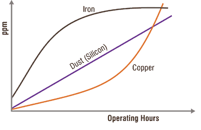 Looking for existing limit sets for specific applications can reveal different results. While limit information may not always be available, there are industrial fields where detailed guidelines exist. Among the groups that set limit values include component manufacturers, original equipment manufacturers (OEMs), oil companies, laboratories, and technical groups and associations.
Component manufacturers often define limits for single parameters that have a direct impact on the component’s lifetime or performance. Examples would include manufacturers of hydraulic components offering recommendations for oil cleanliness or a roller bearing manufacturer stating that a bearing reaches the calculated fatigue lifetime only if the contamination level is within a certain range. This information is valuable, but it is often too general and limited to certain aspects of an oil sample. Nevertheless, component limits are a good reference point if OEM limits are not provided.
If OEM limits are available, they should be considered, especially if they are related to warranty issues. For some types of equipment, detailed OEM limits exist, including information about wear values, oil condition and contamination. Their main purpose is to clearly define the conditions for safe equipment operation.
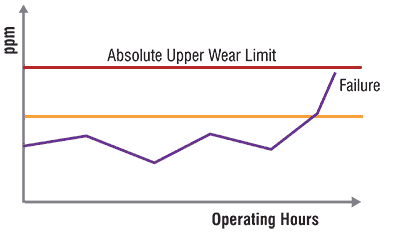 Limit values and evaluation guidelines can also be standardized. Standards may be independent and official, such as those from ASTM, or based on the work of other specialized associations or organizations. Often these limits are available for equipment with strict safety and reliability requirements. In these cases, the limit values should be considered very closely.
Limit values from oil companies are generally focused on oil condition. The main intention is to provide guidelines for detecting when the oil is no longer fit for further use.
Some laboratories use sophisticated computer software to support the creation and administration of equipment- and oil-type-related limit sets based on statistical and trend-based methodologies. Actual samples are connected using a matrix code with corresponding limit sets. This allows a computerized flagging of every parameter. The automated system can increase the speed and quality of the evaluation.
Absolute vs. Trend Limits
The limit information described previously is mainly absolute and does not reflect historic trend development. However, sometimes limit values relating to operating hours or distances are available, especially from engine manufacturers. This means the permissible change of a parameter over time is defined, such as iron per 100 hours of operation. Still, in most cases, absolute limits are valid for a typical overhaul or oil drain interval. If no limit is exceeded, no maintenance actions are necessary and the interval may be extended.
 The evaluation of analysis results based on absolute limits has numerous benefits. For instance, it provides simple handling, quick orientation and can be statistically proven. However, there are also limitations, such as often being valid only for defined intervals. Nevertheless, absolute limits can be effective in some cases. Generally, this is when the failure modes and root causes are known, or the oil property requirements are closely defined and a change in these properties can be directly connected to problems during operation.
The surrounding conditions and the goal of the oil analysis are also important. If the samples are always taken during the oil change and the aim of the analysis is to identify repair actions or upcoming problems, statistically based absolute limit values will be sufficient for the evaluation.
 The longer the oil drain intervals and the higher the priority of a proactive approach for an oil change, the more important trend limits become. This is especially true for oil analysis parameters that are a function of time.
Trend limits offer several advantages, including a more detailed evaluation, greater consideration of historic data and actual operating conditions, and an early warning of upcoming problems.
Of course, trend evaluation is only effective if enough previous samples are available. The sampling procedure and location can also have a significant effect on the final results. For trend evaluation, a sample must always be taken from the same location using the same procedure. If the operating or maintenance conditions change, they also can impact the trend line and must be considered. For most samples from the field, a combination of both methods seems to be the best approach.
 Defining Properly Set Test Methods
Oil analysis can be compared to a puzzle with every piece related to a single test. If only single pieces are available, the complete picture will not be captured.
Oil-aging factors, oil properties, contaminants or wear information depend on the application from which the oil sample is taken. Properly set test methods with sufficient parameters are important to be able to provide the right answers. At the same time, the test set should be as economical as possible in order to support trend-based analysis.
Statistical Methodologies
For the statistical evaluation of limit values based on historical data, two basic methods can be applied: statistical process control (SPC) or a cumulative approach.
SPC Method
SPC is a statistical methodology for the optimization of production and service processes. The SPC theory was developed by Walter A. Shewhart in the early 1920s. Shewhart defined two mechanisms based on the idea that the quality of a product depends on the variation of every part from which the product is made. The first mechanism is a common source variation from the average that is controlled and natural for the process. The second mechanism is a special source variation that is unnatural and can be caused by machine or material failures. These two mechanisms must be clearly identified for a set of parameters that describe the process quality. If the parameter set is normally distributed and the diagram is bell-shaped, the standard deviation can be applied for the definition of limitations.
According to these limits, a decision is possible on whether the variation is normal for the process (common source) or outside the control levels (special source). For production processes, these considerations have led to the introduction of quality cards containing upper and lower control limits. Today, the SPC methodology can be used to control any type of process. In the case of alarm limits based on historical sample data, the standard deviation is also a valuable tool.
Cumulative Method
If the distribution of the measured values does not fit the normal distribution, the standard deviation cannot be applied. This is the case when the mean and median are different or the distribution is skewed or bimodal.
A zero-reference skewed frequency distribution is common for applications where the oil is not changed according to defined intervals and parameters increase over time. Typical parameters include wear, oxidation, acid number, color and contaminants. A high-reference skewed frequency distribution is normal for applications without static oil changes but with parameters that start with an initial value and decrease over time. Standard parameters would include additives, base number and viscosity.
Besides the parameter, the application also has an impact on the distribution of the data. This means that the distribution for every parameter or measured value from a data set must be evaluated in detail and that the same parameter can fit into different distribution schemes for various applications.
| Model | Size | # Sample | FE-Green | FE-Yellow | FE-Red |
|---|---|---|---|---|---|
| A | 1.5 MW | 1804 | <32 | 32-53 | >53 |
| B | 600 kW | 1349 | <106 | 106-149 | >150 |
| B | 1.5 MW | 4762 | <72 | 72-115 | >115 |
| B | 2.5 MW | 2597 | <79 | 79-104 | >104 |
| C | 250 kW | 926 | <26 | 26-78 | >78 |
| C | 600 kW | 495 | <21 | 21-35 | >35 |
| C | 660 kW | 1025 | <22 | 22-42 | >42 |
| C | 1.75 MW | 1183 | <38 | 38-70 | >70 |
| C | 2.0 MW | 4069 | <28 | 28-46 | >46 |
| C | 3.0 MW | 1930 | <30 | 30-52 | >52 |
Practical Examples
The following examples demonstrate how statistically based limits become more precise if the population is broken down to specific machine types. In the second example, the statistical analysis revealed failure modes by drawing attention to the samples with special cause variation.
Limit Values from Wind Turbine Gearboxes
The wind industry has experienced tremendous progress during the last 20 years. The power output of modern wind turbines has increased 50 to 100 times in comparison to the first models of the 1990s. As a result, gearboxes have become much larger. This progress has also had an impact on lubricant requirements and maintenance practices. The trend for modern turbines has been toward high-performance synthetic lubricants. Although the price of these products is higher, their aging stability is significantly increased, which provides an opportunity to reduce the overall maintenance costs by extending oil drain intervals based on oil analysis results. Of course, this means the limit values must be modified.
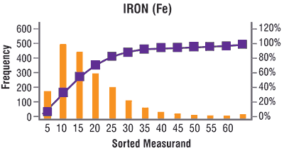
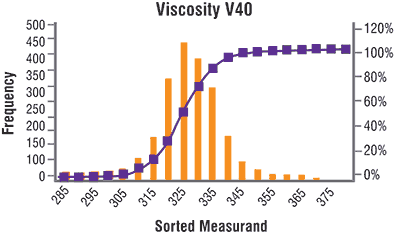
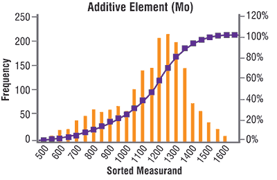
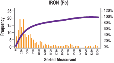
Figures 4, 5 and 6 show the distribution of iron as a wear element, molybdenum as part of the additive system and viscosity as an important parameter for fluid film formation. The distribution of iron is typical for an application where no fixed oil drain intervals are defined. The iron content initially is low but increases over time due to normal wear processes. For this zero-reference skewed frequency distribution, a cumulative method should be applied to define the limit values. The iron range for this population is quite small, which indicates that no significant amount of sample with special cause variation is included. The statistical approach should deliver reasonable limit values.
 The viscosity distribution is bell-shaped. The median and mean are in the same range. SPC and the standard deviation can be used to identify alarm values. Limit values already exist for this parameter based on the ISO viscosity grades. In this case and for this special oil, the limits could be defined more precisely according to the statistical evaluation.
The evaluation of the additive molybdenum also shows a bell shape, but the distribution is slightly high-reference skewed and bimodal. The median and mean are different, which indicates that the cumulative approach should be chosen. The population should also be investigated to identify samples with special cause variation.
Figure 7 contains warning values for iron in different wind turbine models. It illustrates how statistical methods can be much more precise. These statistical-based limits can be combined with trend-based limits to help determine whether an increase in iron is within the acceptable range when compared to the previous sample.
| Type | # Sample | Method | FE-Green | FE-Yellow | FE-Red |
|---|---|---|---|---|---|
| A | 610 | 1 (CUM) | <835 | 835-1850 | >1850 |
| B | 774 | 1 (CUM) | <1508 | 1508-2313 | >2313 |
| C | 1528 | 1 (CUM) | <864 | 864-1331 | >1331 |
| Type | # Sample | Method | FE-Green | FE-Yellow | FE-Red |
|---|---|---|---|---|---|
| D | 2128 | 2 (CUM) | <75 | 75-160 | >160 |
| E | 1291 | 2 (CUM) | <98 | 98-264 | >264 |
| F | 565 | 2 (CUM) | <364 | 364-475 | >475 |
Limit Values for Hydraulic Final Drives
Another example comes from hydrostatic final drives. These systems are used as crawler drives for excavators and agricultural machinery. Oil samples are often taken from these systems during the oil drain procedure with static intervals between 1,000 and 2,000 hours. The main purpose of the oil samples is to confirm that the right lubricant is in use, contamination levels are below permissible limits and wear rates are normal.
In general, the evaluation of oil analysis results for this application is suitable for absolute limit values. Figure 8 shows the distribution of iron for a crawler drive. Results for different models were from the same manufacturer, and for all samples, a comparable oil type was used. The main goal of the statistical evaluation was more precise wear limits.
Figure 9 shows the results of the cumulative method. Unfortunately, the new statistically based warning limits differed significantly from the actual limits in use based on experience. The new calculated limits seemed too high, and the unusual wide range of iron distribution supported this estimation. A closer look at the last 20 percent of the distribution revealed that the data population contained a large number of variations associated with uncommon causes. Two independent but major effects were identified: a loss of viscosity due to contamination with hydraulic oil and high silicon content, which indicated high dust levels due to damaged seals.
Figure 10 shows the statistically based limits for newer models from the same manufacturer. The wear limits are significantly lower and correspond with the previously experienced wear levels for normal conditions. The two problems of the older final drive generation have been solved for the newer generation.
In conclusion, it is important to keep in mind that oil can talk and that limit values are an essential tool for evaluating analysis results from used oils in order to rate a machine’s wear, oil condition and level of potentially harmful contaminants. While limit information can be provided by a variety of sources, in some cases it may not be available. General or global limit sets also are not usually valuable for condition monitoring. Depending on the application, absolute or trend-based limits, or a combination of both, often deliver the best results.
