Integrating Grease Sampling and Analysis Into Wind Turbine Maintenance Programs
Abstract
While oil analysis is a wellestablished part of a condition based monitoring program, the inherent diffculties involved with in-service grease sampling and analysis have long prevented the integration of grease analysis into most CBM programs. Due to this oversight, a sizeable percentage of highly critical machines receive no lubricant analysis and are therefore missing signifcant reliability data. Wind turbines are especially vulnerable to this omission due to the number of highly critical components that are grease lubricated on each turbine. The main bearing, generator bearings, pitch and yaw bearings are all grease lubricated and are traditionally not subject to lubricant analysis, leaving them vulnerable to undetected wear conditions. Recent advances in grease sampling and analysis techniques are leading an expansion in grease monitoring of wind turbines. This paper will discuss recent grease analysis fndings in wind turbine main and pitch bearings utilizing new sampling and analysis techniques outlined in ASTM D7718 and D7918.
Keywords:
Wind; Grease Analysis; Maintenance
1 Wind Turbine Lubrication Maintenance
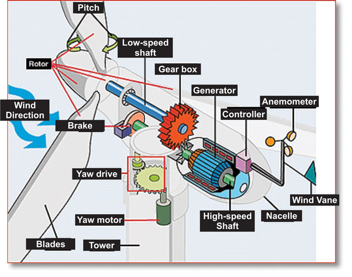
Wind turbines are part of a growing industry of renewable energy. Certain regions of the globe are particularly suited to deploy wind turbines to capture this energy source, and are appearing in ever growing numbers. Much of the maintenance focus on wind turbines to date has been on the transmission gearbox, an oil lubricated speed increaser that takes the relatively slow rotational speed of the turbine blades and converts it to a suffciently higher speed for the generator. While it is appropriate to focus on the transmission, it is by no means the only lubricated component where reliability is a concern. There are no fewer than 6 major grease lubricated components in the majority of large wind turbine designs currently dominating the market. They include the main bearing, generator bearings, pitch and yaw bearings.
For each of these grease lubricated components, failure to function can either interrupt completely, or signifcantly impact the effciency and capacity for electric generation. However, getting a reliable grease sample from these bearings can be a challenge. Finding a solution to grease sampling and analysis challenges can have a signifcant fnancial impact through the early detection of abnormal wear, or the identifcation of degraded or contaminated grease. Obtaining representative samples with useful, low-costs grease analysis solutions is critical to properly maintaining these assets. New grease sampling and analysis techniques have recently been developed in ASTM D7718 and ASTM D7918.
2 Obtaining Samples
 In most circumstances, procedures for obtaining grease samples from the bearing housing and gears are not consistent and likely do not represent the true condition of the “active” grease near the lubricated surface. The grease may also contain particulate and other contamination picked up during the sampling process.
For open gears or rollers, the collection of a sample is best accomplished with a kit that utilizes a spatula-like tool to enable the sampler to gather the grease from between the rollers or open gears. The spatula is used to scrape the grease from the rollers and the grease is placed into a syringe. The flled syringe is injected into the passive grease sampling device [Figure 2]. Because of the non-newtonian nature of grease, it can be diffcult for it to move under vacuum (may be insuffcient to reach the yield stress for flow), therefore during the sampling process the syringe plunger is removed from the body by completely pulling the handle back and out, and the open body is packed with grease using the spatula. The plunger is re-inserted, and the grease can be easily moved while under pressure, to fll the grease sampler [Figure 3].
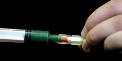 The passive grease sampler design is also optimized for subsequent laboratory analysis. By providing a sealing surface in the ftting cylinder, the entire volume of grease is available for analysis. Extraction of the grease is done under variable pressure and force conditions, and the response of the grease can be measured and related to the grease consistency and flow characteristics of a brand new grease. As the grease is extruded for analysis, it is also delivered on to a thin flm substrate for accurate analysis by FTIR, RULER, spectral analysis, and other tests giving detailed information about grease oxidation, contamination, mixing and wear.
2.1 T-Handle Extension
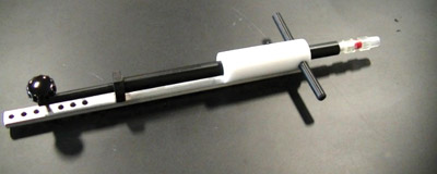 For bearings that must be accessed through a drain port, other sampling tools have been developed. Similar to the principle of a liquid sample “thief”, the device must be able to travel from the access hole to the active lubrication location, near the bearing or gear mating area, and bypass the non-representative grease along the way.
The grease sampler is inserted with t-handle extension to permit remote actuation and capture of the sample at the site of active grease use and wear generation, adjacent to the mating gears or bearing surface.
2.2 Slim Handle
Typical bearing drain port sizes in a wind turbine are around 0.60“ in diameter, but in some main and pitch bearing applications the drain port is smaller and requires a smaller tool for coring the grease sample. The slim tool was designed for drain port sizes ranging from 0.28“ to 0.60“ in diameter.
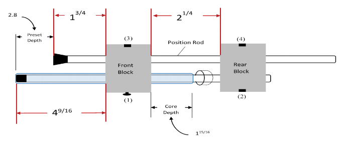
Pocket Slim
The Pocket slim design was created to overcome pitch bearing sampling challenges. Two of the most common sampling challenges with pitch bearings are access to the drain port and clearance at the drain port. The pocket slim design is designed to be used with drain port clearances less than 2 feet. The small design can be used with one hand, allowing the operator to reach if necessary to access the port and core the grease sample. The grease sample is cored with a straw and then transferred into a grease sampler and shipped to the laboratory for subsequent analysis.
3 Basic Analysis Options for Grease
The following tests make up a streamlined grease analysis process that uses the passive grease sampling device outlined in ASTM D7718. This allows the frst two tests to be performed as part of the preparation of the sample for the subsequent tests listed. This reduces the amount of sample handling and preparation required, thus reducing the potential costs of performing meaningful and routine grease analysis for critical equipment [3].
3.1 Ferrous Debris Monitoring per ASTM D7918
A diffculty in evaluating wear particulate in grease exists because of the inability to agitate a sample to evenly distribute particulate, as is done with oils. This non-uniformity of distribution can lead to misleading results because the portion of the sample selected for dissolution and analysis may be skewed higher or lower with respect to wear particle content. One way to compensate for that condition is to measure the ferromagnetic effects of the grease by inserting the passive grease sampling device into the center of a magnetic feld generated by a coil. This method minimizes data scatter due to particle distribution issues and improves trendability and sensitivity of results.
3.2 Grease Consistency per ASTM D7918
By measuring the load under varying conditions during the extraction of the grease through the extrusion die, the consistency of the grease can be compared to the new grease consistency. Changes in this value, whether indicating a thinning or thickening of the grease, can be used to flag this property. Subsequently, the grease is distributed on to a thin flm substrate in 0.25 gram sections that can easily be distributed to other instruments in the laboratory for further testing. Follow up detailed analysis with a rheometer can further classify the condition of the grease and gives detailed insight into the flow and shear behavior of greases under dynamic conditions.
3.3 Comparative FTIR Spectroscopy
FTIR spectra are created from new grease samples for all greases in a facility’s program. Using a horizontal attenuated transverse reflectance (HATR) rig, a thin flm of grease is applied across the crystal. The in-service greases are tested and compared to a new grease spectrum. In particular, for different families of greases, the FTIR spectra are quite different and can be compared to see if signifcant mixing has occurred. In other cases, similar greases (two different polyurea greases) might not have signifcant differences in their spectra, but there is less likelihood of compatibility issues in that case. Still, many greases within the same family from different manufacturers can be differentiated with FTIR analysis. Also this test is valuable in monitoring for grease oxidation and the presence of certain organic additives.
3.4 Anti-Oxidants
The RULER instrument works on the principle of linear sweep voltammetry. By applying this test method, in which a variable voltage is applied to the sample while measuring the current flow, the presence and concentration of various antioxidant additives (including, but not limited to ZDDP) can be determined based on their unique electrochemical oxidation potential and the magnitude of the induced current. Monitoring residual anti-oxidants in purge greases can provide feedback on the effectiveness of grease relubrication frequencies. For example, a grease sample that has been purged from a bearing on the established relubrication interval, when analyzed and determined to have a large amount (perhaps 70% or more) of residual anti-oxidants, and also shows good consistency characteristics, may be a candidate for extension of relubrication interval. Conversely, a purge grease sample that shows no or minimal (less than 25%) residual antioxidants may not be completely protected from oxidative stressors during the grease life-cycle, and may appropriately be adjusted to a shorter relubrication interval.
3.5 Metals Spectroscopy
The grease is weighed out or distributed onto the thin flm substrate and added to a glass vial where it is diluted and dissolved with a fltered mixture of grease solvent. This liquid mixture is then analyzed by RDE (Rotating Disc Electrode) or ICP (Inductively Coupled Plasma) spectroscopy, and the results are ppm normalized to 1 gram of grease based on the measured weight of grease that was dissolved. The concentration of metals in the grease can be compared to the new grease for the purpose of identifying signifcant differences in additive metals that could point toward grease mixing. Also, the presence of wear metals can be deduced.
3.6 Grease Colorimetry per ASTM D7918
Visual observations of grease appearance are a common assessment tool for feld evaluation of lubricated components. Appearance changes, including darkening and unexpected or mixed colors, are often the frst condition noted that may indicate unusual lubrication conditions or mixing. A desire to empirically evaluate and substantiate such observations led to the development of an optical cell, used to present a grease sample in a uniform manner for subsequent visible light spectral analysis. This grease colorimetry optical cell is designed to create an optical path for the visible light spectrometer, and includes a sliding drawer that presents the extruded grease thin-flm on substrate produced from the Die Extrusion Method. The resulting 0.040” (1.0 mm) pathlength is backed by a polished stainless steel mirror, which allows testing of the grease in a uniform manner without interference from ambient light and without contacting the grease sample.
It has been suggested that grease colorimetry may have value in the manufacture of greases. Current commercial greases typically are dyed, for differentiation and marketing purposes. The specifc color of a grease becomes closely identifed with the brand, and maintaining consistency in the color of the product, while not affecting performance, may be important from a perception standpoint. Batch testing of greases by comparing an in-process batch with a colorimetric profle may enable grease manufacturers to quantitatively evaluate color and include a quality control step on appearance as part of the process.
4 Data Integration and Advanced Analysis
Together these tests can be used to evaluate the condition of the grease, determine the extent of mixing with an incorrect grease, detect oxidation, measure the depletion of anti-oxidant additives, and categorize the extent of wear present in the sample. These tests can be done cost effectively because the consistency measuring instrument prepares the grease as a thin-flm substrate for weight normalization and easy dissolution of the grease thickener, so the liquid sample can be analyzed with typical oil analysis equipment.
4.1 Additional Testing
If concerns arise during the above analysis test slate, follow-up analysis can be performed using the following tests:
Analytical Ferrography
This test can also be performed on the dissolved grease (prepared as for metals spectroscopy) to visually identify the amount, shape, composition, and wear severity of the particulate in the sample. This method and its benefts are well documented for oil analysis, and have similar benefts for properly obtained grease samples. The key difference for greases is that it is necessary to understand that wear levels are cumulative during the operating life of the grease, and that relative quantities of observed particulate can be misleading, if comparing samples with signifcant differences in service time for the grease.
Patch Microscopy
When the particles of interest are non-metals or non-ferrous metals, there may be some advantage to preparing a Millipore patch by drawing a diluted sample under vacuum through the patch and microscopically analyzing the particulate content to identify the presence of wear or contaminant particles, and relatively quantifying their presence. Often, this test is more diffcult with greases than oils, because of the diffculty in completely dissolving grease thickeners suffciently to pass through the patch. Solvent selection is critical, and some grease thickener types do not perform well in this test, with the presence of thickener fbers dominating the flter patch and obscuring other particulate.
Grease Rheology
Use of a rheometer and evaluation of such parameters as normal force measurement and apparent viscosity can be signifcant in the characterization of grease properties. Prior research [1,2] has indicated the value of applying rheological measurements to both new and used greases, and research is ongoing to optimize this analysis and relate measured parameters to changing physical properties. Rheological measurements provide insight on changes due to incompatible grease mixing, excessive grease working, and severe oxidation. One of the capabilities of this testing is the ability to evaluate the compatibility of mixed greases. The data results of this test provide insight into grease pumpability, shear characteristics, and the tendency for a given grease or grease mixture to undergo “channelling” or “tunnelling” in bearing and gear applications.
5 Grease Sampling and Analysis in Wind Turbine Applications
5.1 Pitch Bearing Grease Sampling and Analysis
Recently grease sampling and analysis was performed on a series of failed pitch bearings where it was thought the incorrect grease was originally packed in the bearing by the manufacturer. Grease samples utilizing the slim handle technology were taken from the failed bearing , and returned for lab analysis. In addition, grease samples were taken from other similar bearings removed from service at the same time as well as broken pieces of the cage. Samples were taken from the supply holes on the outside of the outer race as well as through the seal for a comparison of the results and an evaluation of candidate locations for sampling moving forward. The elemental comparison and FTIR analysis showed there was a signifcant residual concentration of Grease A in the supply hole samples, even after the recent product change over to Grease B. The signifcant differences observed between the area below the seal near the rolling elements and the samples taken from the supply hole indicated the grease from the supply hole is part of the non-active region, and was likely not a good indicator of the bearing condition. The seal samples showed much higher wear levels in addition to a better comparison to Grease B, which would indicate these samples were in a region actively participating in the lubrication of the bearing. It was determined moving forward samples from the seal would likely give a better indication of the condition of the bearing.
Additionally, physical inspection of the broken cage piece showed dark grooves on the surface of the cage facing the rolling elements. Advanced ferrographic analysis of the grease seal samples confrmed the presence of black oxides indicating high localized temperatures due to skidding and loss of lubricant flm condition. In a low speed high load application, such as this, it is possible full flm conditions are never established in the bearing, in which case an anti-wear or extreme pressure additive is critical to provide protection for the contact surfaces. The presence of white solids in the formulation of Grease B were intended to provide this protection against boundary lubrication damage. The continued presence of Grease A; however, raises concern about the effectiveness of the product changeover from Grease A to Grease B. A continued purge and replacement with Grease B was suggested.
5.2 End of Warranty Fleet Testing
US wind turbine owners used grease analysis to evaluate their fleet of turbines nation-wide coming off of warranty. Full grease analysis of one wind turbine is approximately $500- $750 per year. When these problems are encountered early with grease analysis, the problems can typically be fxed uptower for less than $2,000. If a bearing failure occurs, the cost for replacement can be $350,000 or more (for off-shore). Grease analysis is an excellent tool for early indications of wear and grease consistency problems. It can also be used to optimize relubrication frequency and save on grease changeouts.
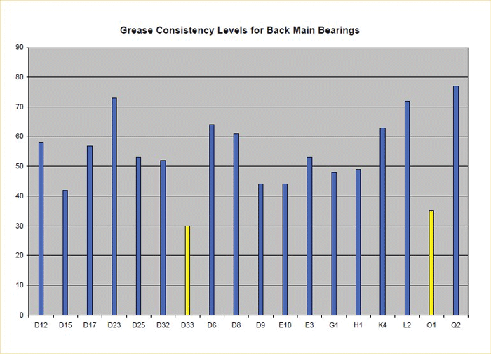
Figures 6 and 7 shows some examples of how grease analysis is used to detect consistency and wear levels in a fleet of samples. Consistency changes are often indicative of other problems occuring with the grease. Grease mixing is the most common reason for changes in consistency. Other reasons can include excessive load or even excessive wear particulate.
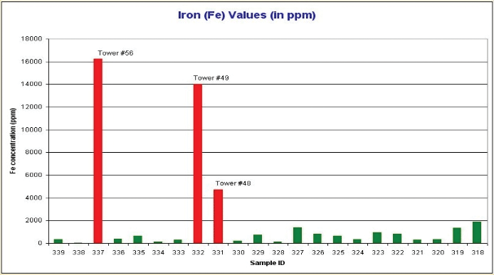
Trending wear levels is also extremely important. Changes in the wear values can indicate excessive surface or cage wear. The fdm+ technology is a useful tool for screening grease samples for further wear testing such as metal spectroscopy or analytical ferrography to understand the nature and origin of the wear particulate. The fdm+ technology paired with the passive grease sampling device is an excellent way to trend the wear levels and ensure a representative sample is being taken from the same location on the bearing each time.
6 Conclusion
Grease analysis presents a signifcant opportunity to expand machinery diagnostic capabilities. The historical challenges of obtaining representative and trendable samples are being addressed through technological developments outlined in ASTM D7718. The further development of repeatable analysis methods outlined in ASTM D7918 utilize smaller quantities of grease; which produces greater value in the analysis results and encourages the sampling of greases from locations where reliability is important. By designing grease sampling equipment appropriately, the matter of optimal grease replenishment may also be addressed through the establishment of sampling programs. Wherever there is a critical machine, regardless of lubricant type, the demand for reliability drives the development of improved sampling methods and analysis techniques to produce the valuable information present in lubricant analysis.
References
- Nolan, S., Sivik, M., “The Use of Controlled Stress Rheology to Study the High Temperature Structural Properties of Lubricating Greases,” NLGI 71st Annual Meeting, Dana Point, CA, 2004.
- Johnson, B., “The Use of a Stress Rheometer in Lieu of Cone Penetration,” NLGI 74th Annual Meeting, Scottsdale, AZ, 2007.
- Wurzbach, R., “Streamlined Grease Sampling and Analysis for Detection of Wear, Oxidation and Mixed Greases”, NLGI Annual Meeting, Williamsburg, VA, USA, June 2008.
About the author
Lisa Williams has been with MRG Labs since 2007 working both in the lubricant laboratory and on-site with clients to manage lubrication programs. She is certifed by STLE as a Certifed Lubrication Specialist (CLS) and also holds ICML MLA I and LLA II certifcations. Ms. Williams serves as Co-Vice Chair of ASTM D02.96 Committee for In-service Lubricant Testing and Practices. During her time at MRG, Ms. Williams has developed three patents and successfully balloted two ASTM standards (ASTM D7918 and ASTM D7718) related to in-service grease sampling and analysis
Lube Tips: Slight Changes Can Mean Big Problems
Copper readings can be particularly alarming when increases are in the hundreds of parts per million. However, huge increases are typically insignifcant in terms of component wear. Ironically, small subtle increases in copper are of greater concern and should be examined closely. Copper alloy component wear is generally accompanied by lock-step increases in alloy metals such as lead, tin, aluminum and zinc. The amount of alloy metal present in brass/bronze components is only a small percentage of the total copper content. Changes in these alloys may be only a few parts per million but should be taken seriously when present with copper increases.
Controlling Contamination
Portable transfer/flter carts are versatile and can be used for more than just transferring fluids. Other possible uses include offline fltration, cleaning stored lubes, flushing after machine repair and rebuild, flushing during equipment commissioning and draining a reservoir or sump.
Greasing Gearbox Bearings
Does your gearbox have a sealed or open input shaft bearing? This bearing is often above the gearbox oil level and must be greased if it is an open bearing. Manufacturers may ship the gearbox with a plug where the grease ftting is needed to prevent damage during shipping.
In addition, the manufacturer may change the input shaft bearing design from open to sealed and back to open without notifcation. Small changes such as no longer receiving an attached plastic bag with a grease ftting included with the replacement gearbox may be a clue to a change in design.
Always check the manual included with the new gearbox to see if the lubrication needs have changed.
Advice for Coupling Grease Application
When changing the lubricating grease in a geared motor coupling, always apply a full coating of grease to the teeth of the coupling. Never fll the coupling housing completely with a grease gun due to expansion of the grease as the motor comes up to running temperature.
This expansion of the grease will apply internal coupling pressure, pushing the motor shaft off magnetic center and onto the thrust surface of your bearing, causing bearings to overheat and leading to early bearing failure.
Even after hand-packing the coupling, the motor should be run up to operating temperature, then shut down and the grease plug removed to allow excess grease and pressure to be released.
Inspect Your Level Gauges
Routinely inspect the vent hole in column-type vented level gauges. In dirty environments, the vent hole can become easily plugged, causing an air lock in the gauge headspace. This will result in a false oil level (higher than reality) in the gauge. Many prefer dualport gauges instead (unvented).
‘Handy’ Sampling Tip
During regular weekly or monthly oil sampling, use a tube of “handy wipes” to keep your hands cleaner while handling sample equipment. This practice may not show directly in the cleanliness of the samples, but it feels cleaner, looks very professional and sends a message about the importance of contamination control.
Keeping Hydraulics Healthy
Baffles are an important component in a hydraulic reservoir. They allow the fluid time to cool, deaerate and to settle out water and dirt. A good rule of thumb for residence time in a reservoir is three to fve times the pump output. If the system is highly contaminated, residence time may be 10 times the gallons per minute of the pump.
