Case Study: 30 Years Without an Oil Change
 Thirty years without a complete oil change usually would be considered impossible. In this case, there was makeup fluid over the 30+ years, which amounted to slightly more than the system volume on each of the two units. The testing parameters for acid levels, particle counts, water and conductivity were maintained within specifications with a few exceptions. Varnish was identified, but no exclusive tests such as membrane patch colorimetry (MPC) or quantitative spectrophotometric analysis were conducted to confirm or quantify the amount of varnish. Of course, the 30 years without an oil change did not come without consequences, as was discovered after the system flush and chemical cleaning were completed.
The System and Components
The Seminole Electric Cooperative is a two-unit, 1,300-megawatt coal-fired generating station south of Jacksonville, Florida. The electrohydraulic control (EHC) reservoirs and systems are larger than normal, utilizing 2,400 gallons of fluid per unit. Three 170-gallon-per-minute submerged screw pumps are located in the reservoir. When required, they provide flow at 580 pounds per square inch at the turbine level. There are 10 control-valve and 10 stop-valve hydraulic actuators on the high-pressure, intermediate-pressure and low-pressure turbines. A full-flow filter offers 25-micron filtration up to the turbine actuators, while an acid-remediation and 1-micron polishing filter skid runs in kidney loop off the reservoir. Two 2,400-watt heaters in the filter skid sustain the fluid temperature when the system is offline. Super-dry air is supplied to the reservoir headspace for maintaining the moisture level in the fluid. Tube and shell coolers keep the fluid temperature at the desired level.
System Flushing and Cleaning
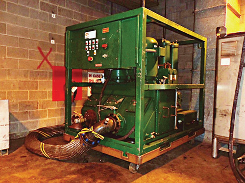
Due to the complexity and size of the system, an outside company was contracted to perform the flushing and cleaning. A large 300-gallon-per-minute pump/filtration unit would provide the circulation. A large quantity of fittings, flanges, jumper hoses and valves was required to flush the system. For a true high-velocity flush, the fluid was circulated at five times the normal flow rate to achieve turbulent flow through the piping and components. This was accomplished by running sections or circuits rather than the entire system during the oil flush.
To help with the cleaning process, the oil was heated and temperature cycling was performed. No filtration was done during the cleaning process. Particle counts were taken in the beginning for a baseline and after the completion of each system process. The particle counts usually spiked rapidly and then began to level out as the process proceeded. Once three consecutive particle counts remained level or dropped slightly, the flush/cleaning was stopped. All fluid was drained from the system, air was blown through the piping to help remove any trapped fluid, and the vessels that could be opened were cleaned and wiped out, including the reservoir. Time was of the essence, as the fluid would begin gelling as it cooled, making it harder to remove and clean.
The Rinse Cycle and the New Fluid
 After the entire system was drained and wiped down, the reservoir was filled with a lesser value phosphate-ester fluid, which was used to rinse and clean out the system. Approximately three-fourths of the tank volume or 1,600 gallons were used for the rinse. This was completed in the same manner as the flush, utilizing different system sections or circuits. This time the fluid was filtered as it ran through the system. Particle counts were taken at the end of each complete system cycle. Once the desired particle count was reached for three consecutive cycles, the rinse was completed. The rinse fluid was then drained and saved in large totes for use on the second unit’s flush. Piping was blown out, and the reservoir and all vessels were opened and wiped down. New filters and acid-remediation media were also installed. The system was now ready for the new fluid.
 Of the new EHC fluid, 1,600 gallons had been transferred to large totes from the drums and flowed through a polishing filter for several days. The remaining 800 gallons were pumped through the filter skid when it was installed in the reservoir. Since the unit was not able to be run when the project was completed, a filter skid was kept onsite and used on the reservoir through the commissioning of the system and valve setting. Once particle count levels were acceptable, the filter skid was removed and the system filtration was resumed.
When the system was returned to service, a few minor leaks and loose flanges were reported. Of the hundreds of fittings and flanges that had been opened, bypassed and reassembled, a few leaks were expected.
The Aftermath
 The second unit’s flush was completed first. The fluid manufacturer, oil analysis lab and others were contacted to determine which tests could be conducted to confirm that the cleaning agent had been thoroughly removed, which was a concern at the time. All tests indicated that everything was good to go.
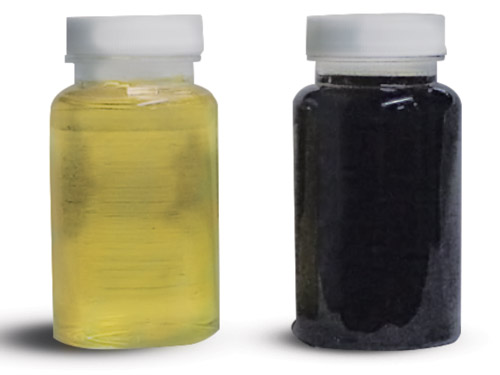
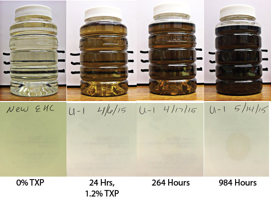
The new fluid was expected to darken slightly once it began circulating, but this occurred much quicker than anticipated. Since ester has incredible cleaning properties, the assumption was that it was removing residual buildup that remained after the flush. When the fluid continued to get darker and darker, the fluid manufacturer was contacted to see what other tests could be performed to verify the additional cleaning of the system.
 The old fluid contained trixylyl phosphate (TXP) and aryl phosphate, which the new fluid did not. The manufacturer suggested a gas chromatography test to see if TXP was present in the new fluid. If so, it could be presumed that the old material was being removed from the system internals.
The first test for TXP on the second unit occurred in December 2014, approximately eight months after the flush. The TXP levels came in at 2.2 percent. The next test for TXP took place in October 2015. The TXP levels were now 1.87 percent. The question was whether the levels were actually decreasing or were the results within the percentage of deviation for the test.
What Is EHC Fluid?
Electrohydraulic control (EHC) fluids are typically fire-resistant lubricants, which are important in applications where hydraulic fluids can be exposed to high temperatures or sources of ignition, such as power generation, furnaces, foundries, and military and aeronautical applications.
What is a fire-resistant fluid? According to ExxonMobil, “fire-resistant hydraulic fluids are specially formulated lubricants that are more difficult to ignite and do not propagate a flame from an ignition source. Fire resistant should not be confused with fireproof, as fire-resistant fluids will still ignite and burn given specific conditions.”
Fire resistance is defined by ISO 12922, rev. 2 (2013), which evaluates fluids based on three tests selected to represent three different fire scenarios: spray flammability (ISO 15029-2), wick flame (ISO 14935) and hot manifold ignition (ISO 20823). The difference between some of the fluids as tested, based on ISO 12922 rev. 2, is whether they will self-extinguish once the heat source is removed.
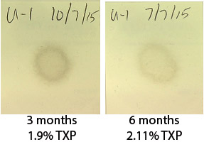
After the second unit’s flush and TXP testing, preparations were made for the first unit. Its TXP levels at 24 hours of circulation were 1.2 percent. At three months, the levels increased to 1.9 percent, and at six months, they rose to 2.11 percent. The tests correlated with a darkening of the fluid as well as an increase in the blotter test rings, the MPC color and the weight of the patches. Although the particle counts were within the specified range, only particles greater than 4 microns were measured. It was apparent that submicron particles were involved, which normal filtration would not remove.
The next step in the process will require specialized testing to determine the particulate makeup. Knowing if the composition includes oxidation byproducts, inorganics or carbon/soot from micro-dieseling will be critical in choosing the best method for removing it from the fluid. Depth media, electrostatic filtration and a specialized blend of ion-exchange resins are some of the methods generally considered for varnish or submicron particle removal. Each claim to have advantages over the others for different types of particles.
One problem with a 2,400-gallon reservoir is the turnover rate when utilizing side-stream or kidney-loop filtration. With most of these technologies, slower flow through the media or elements is required for them to work properly. A 10-gallon-per-minute system would only turn over the reservoir volume of 2,400 gallons six times in a 24-hour period. Normally, with sideline or kidney-loop filtration, it is believed that seven times the reservoir volume turnover is equivalent to one-time full-flow filtration. To get ahead of the problem, it is suggested that a reservoir be turned over at least three times per day, which would require a large 30-gallon-per-minute system or several smaller systems running in parallel.
In conclusion, the law of unintended consequences, which states that actions always have effects that are unanticipated or unintended, wins again. In performing an industry-accepted practice of a high-velocity chemical cleaning and system flush, it was discovered that the system’s age and buildup were a problem. Once the particle makeup is identified, the source of the particles can hopefully be reduced or eliminated, and the process of cleaning the system can begin. Will this be a one-time cleanup or will the system require constant, specialized filtration to keep it in pristine condition? Only time will tell.
