How to Select a Lubrication System for Process Industries
Proper lubrication requires two main considerations: the correct choice of lubricant and the most efficient way of applying it. Failure with either selection can result in a major equipment malfunction. This article will describe how to select the right lubrication system for any process plant.

Manual Lubrication
 The vast majority of greasing points are manually lubricated. During the last 15 years, several new products have been introduced to ease the lubrication technician’s work, including grease meters, cordless grease guns and computer-monitored greasing systems that employ radio-frequency identification (RFID) technology to identify lube points. There are also systems that use acoustic aids to sense when the lubricant has reached the rolling edge of the bearing.
All of these products have made manual greasing more reliable. Today, no lube tech should be forced to perform his job with only a manual grease gun and count strokes to obtain the correct amount. At the very least, the technician should have a grease meter. If the plant has a large number of lube points, a cordless grease gun would also be of great help.
Automatic Lubrication Systems
Automatic lubrication systems are designed to eliminate manual labor costs while allowing the machine to be lubricated during normal production. These systems can also minimize the risk of lubricant contamination, avoid potential hazards associated with manual lubrication and provide better control of the amount of lubricant dispensed. A variety of system configurations are available, including dual-line, single-line volumetric, single-line progressive and single-point systems.
Dual-line Systems
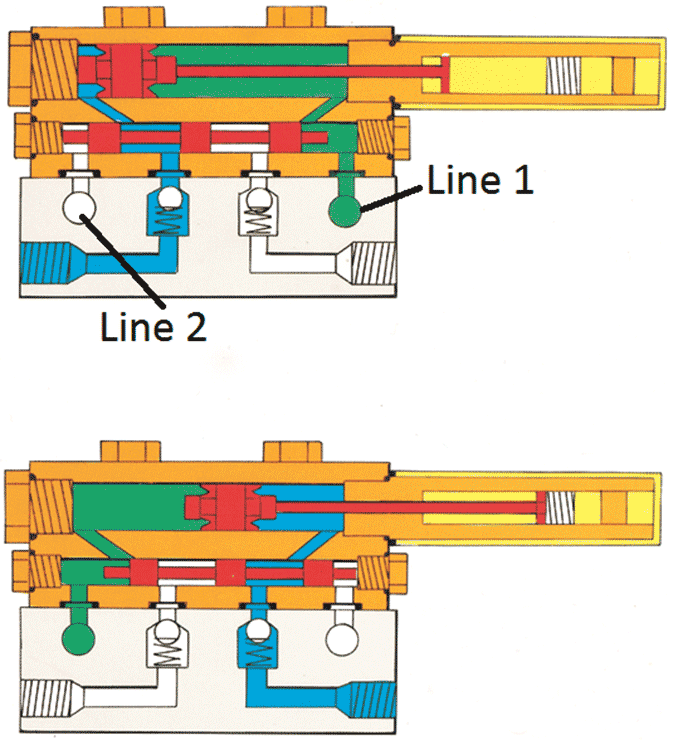
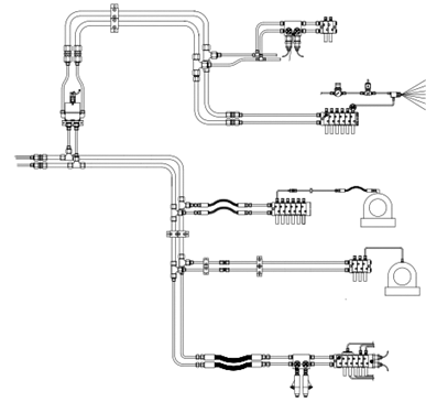 The dual-line system is the predominant lubrication system in heavy process industries. These systems are very reliable, simple to understand and maintain, and allow you to easily expand or reduce the number of points. Their name comes from the fact that they have two main distribution lines.
Pressurized lubricant entering the dispenser from line 1 forces the pilot piston (the lower one) to the left, allowing pressure to be applied to the right side of the main piston. The main piston then begins to move to the left. This dispenses the lubricant on the left side of the main piston through the pilot piston and the check valve to the bearing connected to the outlet.
Pressurized lubricant entering the valve from line 2 forces the pilot piston to the right, allowing pressure to be applied to the left side of the main piston, which begins to move to the right. In the same manner as above, the main piston forces the lubricant on the right side to pass the pilot piston and the check valve, and then reach the bearing via the outlet.
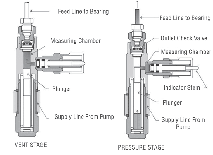
The illustration on the left shows one version of a dispenser design used for both oil and grease. When pressurized, the plunger forces the lubricant in the measuring chamber out to the bearing. In the upper position, the measuring chamber loads with a preset volume.
 Single-line Volumetric Systems
Single-line volumetric systems require only one header line. They are generally used for oil lubrication, but there are some models specifically designed for grease. Like dual-line systems, single-line volumetric systems are simple to maintain and understand, and the number of points can be easily expanded or reduced.
In these systems, the dispenser must reload after a lubricating cycle. This means the piston in the dispenser must overcome the lubricant pressure in the pump line. The models designed for grease are equipped with strong springs that allow reloading of the dispenser at relatively high venting pressures.
Single-line Progressive Systems
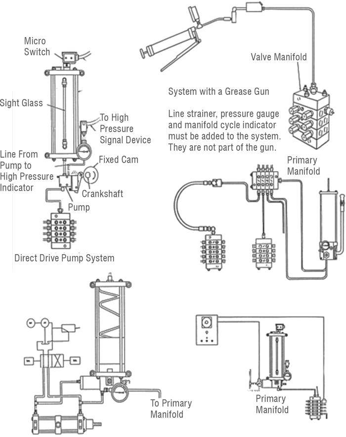
The heart of a single-line progressive system is the progressive divider. It has at least three dispensing elements, each with a hydraulically driven spool that feeds a fixed amount of grease during the stroke from one end to the other. The volume is defined by the diameter and length of the piston stroke, which cannot be adjusted. The spools are internally connected through a cross-porting arrangement that forces them to work in sequence, one after the other. If one spool is not able to fulfill its stroke, the divider will stop working.
These systems are often designed with one primary divider and a number of secondary dividers. Monitoring one spool in any of the dividers will give full control of the whole system, provided there is no leakage in the tubing from the divider to the wear surface.
Single-line progressive systems offer flexibility and can be used alone or in conjunction with other systems, such as direct-feed, dual-line and manual systems. They can handle both oil and grease, and are less expensive than dual-line systems. However, these are large systems with several secondary dispensers, so they can be more difficult to maintain and understand.
 Single-point Systems
The first automatic single-point lubricators consisted of a spring-loaded piston that was charged with grease. The spring extruded the grease through an orifice, with flow dependent on the orifice, the spring force and the stiffness of the grease. These factors limited the spring-activated models, which have had only a limited impact on the market.
Single-point Lubricators
During the last 20 years, new single-point lubricators (SPLs) have been introduced and have increased in popularity. The latest SPLs are easy to install and do not require a significant financial investment. Simply screw the unit onto the lube point, set the operation time and start it. The operation time generally can be set from one month to 12 months. While managing a single-point lubricator may sound simple, it is quite easy to ruin a bearing or the entire machine if you are not knowledgeable about these devices.
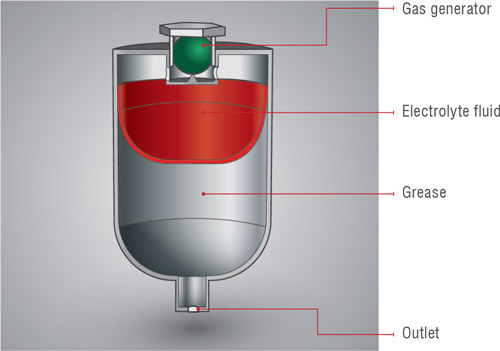
There are three basic models of SPLs: gas-activated, motor-driven and spring- activated. The gas-activated version involves a chemical reaction that expands a gas. This reaction is initiated by releasing a gas generator into the electrolyte fluid. The increased pressure of the gas is transformed onto the lubricant in the container, thus forcing the lubricant to flow out to the lube point. A typical maximum pressure of a gas-powered lubricator is 75 psi (5 bar), but in some models it may be as low as 15 psi (1.5 bar).
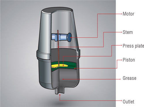
The second type of single-point lubricator consists of a piston on top of the container and an electric-motor-driven mechanism with a stem that forces the piston into the container and thus the lubricant to flow out. These models are usually able to reach somewhat higher pressures than the gas-driven versions, with normal pressure ranges from 72 to 145 psi (5 to 10 bar).
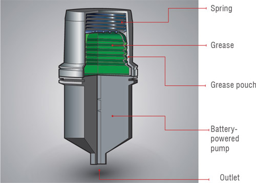
The third type of SPL contains a small piston pump that sucks from the container and feeds directly out. These models can reach pressures of 425 to 850 psi (30 to 60 bar).
Using a single-point lubricator of any type requires treating batteries or the used lubricator as waste. Disposal of this waste must be considered when choosing the type of equipment to be used.
Manual vs. Automatic Lubrication
 It is important to strike a balance between manual and automatic lubrication. Manual lubrication with a high-quality lubricant may be best for lube points that require infrequent relubrication, such as monthly intervals or longer. However, avoid manual lubrication of points with short lubricating cycles whenever possible.
Although manual lubrication can be expensive, replacing it could be even more costly. While lubricating manually, technicians may also observe the machinery and can report or even fix irregularities. Pay special attention to manual points that are difficult to reach. If lubricant cannot be applied in a safe manner, an automatic lubrication system may be the only solution.
 Converting manual points for automatic lubrication will require an investment estimated at approximately $650 per point. While this conversion cost may be discouraging for some, keep in mind that automatic lubrication can result in a more reliable system with fewer bearing failures. Any investment in an automatic system must also be compared with the expected return on investment from the elimination of labor costs, better control of lubricant dispensing, and the reduction of potential health and safety costs.
Which System Should You Choose?
Deciding how to lubricate equipment in a process plant is not an easy task. There is generally no accepted rule for how this can be accomplished. To develop a strategy for the relubrication of each lube point, you must consider several factors, such as the consequences of a bearing failure, the lubrication cycle, the ability to lubricate manually and the hazards of relubricating during a normal production run.
 The consequences of a bearing failure can be classified for both automatic and manual lubrication. Although no common standard exists, you can create your own classification, which could be similar to the following:
| Class 1 | Less important points that do not affect production and are easy to repair or replace |
|---|---|
| Class 2 | More important points that affect production and/or are difficult or time-consuming to replace |
| Class 3 | Important points that affect production and/or are expensive to repair or replace |
| Class 4 | Critical bearings that directly affect production and must not fail |
For each class, define which lubrication systems are acceptable and how performance is verified. Classes 3 and 4 are the most interesting. If the lubrication system does not work properly for these classes, sooner or later you will experience costly problems.
For class 3, only reliable lubrication systems with good control functions should be used. Note that most systems only monitor the pressure in the main distribution lines or that the piston has moved in the dispenser. None of the traditional systems can indicate whether the lubrication pipe between the dispenser and the lube point is broken.
For class 4, ensure that the amount of lubricant fed into the point is measured and compared with the set value, or that vibration measurements are collected on a regular basis and studied, with appropriate action taken when necessary.
Finally, do not overlook the training of your team members. Maintenance personnel must be familiar with all types of systems in use. Lubrication systems can fail and need repairing. Therefore, it is wise not to mix many different system types and brands. This could result in choosing a dual-line system for just a few points when a single-line progressive system would be less expensive.
