How Directional Valves Affect Oil Flow in Hydraulic Systems
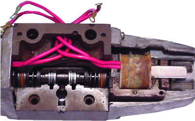
Directional valves are some of the most fundamental components of a hydraulic system. When a directional valve is sized for an application, it must be large enough to handle the volume of oil necessary to operate the cylinder or hydraulic motor. For applications that require less than 10-15 gallons per minute of oil flow, a direct solenoid-operated valve is used (as shown in Figure 1).
To shift the valve spool, current is applied to the valve coil. This creates magnetism within the coil, which pulls in the plunger. The plunger then acts on a pushpin, which shifts the valve spool. The solenoid generates approximately 30 pounds of force to shift the spool. Once the spool shifts, oil is ported through the valve and then to the cylinder or hydraulic motor.
 Two-stage Valves
On systems where higher flow rates are required, two-stage valves are normally employed. A typical two-stage proportional valve is shown in Figure 2. The top valve is known as the pilot valve. The purpose of the pilot valve is to direct pilot pressure to shift the main spool. Since these are larger in size than the direct operated valves, more force is needed to shift the main spool. Instead of using very large solenoids that demand high current to operate, hydraulic pressure is utilized to shift the main spool.
There are springs on both sides of the main spool which hold it in the center position when the pilot valve is not shifted. The springs are usually rated between 50-115 pounds per square inch. When the main spool on this particular valve is in the center position, the “P,” “A,” “B” and “T” ports are blocked.
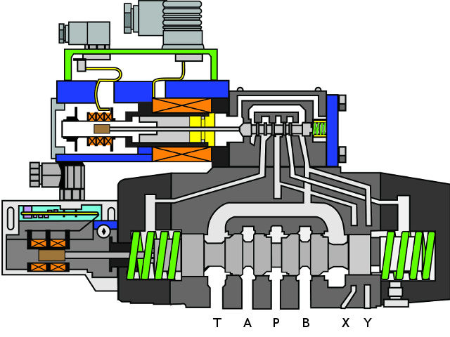 Two-stage valves may be internally or externally piloted. In Figure 2, notice the pilot plug (circled in red) on the left. This plug blocks flow from the “P” port of the main spool to the “P” port of the pilot valve. When this plug is installed in the valve, pilot pressure must come from an external source and be connected to the “X” port on the valve manifold.
Many presses and mobile equipment employ a separate pump for supplying the pilot fluid. In some cases, oil is ported downstream of the pump through a pressure-reducing valve and then to the “X” port. By utilizing a separate pump or pressure-reducing valve, a lower pressure is used to shift the main spool. This prevents damage to the spool instead of using the higher system pressure to shift the valve.
When current is applied to the pilot valve coil (as shown in Figure 3), magnetism in the coil causes the pilot spool to shift to the right. Pilot fluid then flows from the “X” port through the pilot valve and to the pilot cavity on the right side of the main spool. Once the pilot pressure builds up enough to overcome the spring acting on the opposite side, the main spool will shift to the left.
Once shifted, the system volume at the “P” port of the main spool will flow through the “P” and “A” ports and then to the actuator (cylinder or hydraulic motor). The oil that exhausts out of the actuator flows into the “B” port, which is connected to the “T” port inside the valve. The oil will then flow out of the “T” port and return to the reservoir.
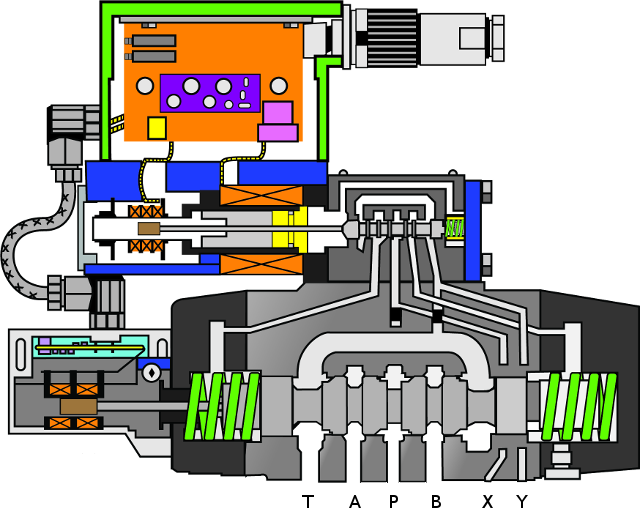 When the main spool shifts (as in Figure 3), the oil on the left side of the spool is ported through the pilot valve spool. Notice in Figure 2 that the circled pilot plug on the right is blocking the flow passage from the tank port of the pilot valve to the tank port of the main spool. When this plug is installed, a line must be connected to the “Y” port on the manifold to externally drain the valve. This provides a flow path for the oil that exhausts out of the main spool’s pilot cavity and pilot valve to return to the tank.
In some instances, both pilot plugs are removed from the main valve housing. In this case, there are no external lines connected to the “X” and “Y” ports on the valve manifold. In Figure 4, the pilot plugs have been removed. This opens the internal pilot passage from the “P” port of the main valve to the “P” port of the pilot valve. Once the pilot valve is shifted, system pressure is directed through the pilot valve to shift the main spool, as previously.
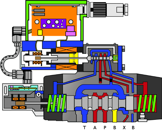 When the main spool shifts, the oil that exhausts out of the opposite pilot passage will flow through the pilot valve and then into the tank line of the main spool. This is what is known as an internally piloted and internally drained valve. Valves can be internally drained as long as there are no flow surges or pressure spikes in the tank line that affect the shifting of the main spool.
Replacing Two-stage Valves
When replacing a two-stage valve, it is important that the piloting and draining arrangements are the same as the removed valve. This applies to proportional and AC voltage-operated valves. In certain instances, valves are internally piloted and externally drained. In other cases, they may be externally piloted and internally drained. Refer to the valve’s part number to ensure the valve you are installing is the same as the one that was removed.
Just because it mounts on the same manifold does not mean it is the same valve. For example, a closed-center, externally piloted and drained Vickers valve has the following part number: DG5S8-2C-E-T-30. The “E” designates that the valve is externally piloted, while the “T” indicates that it is internally drained. If a DG5S8-2C-E-30 valve is put in its place, the valve will not work because it is externally drained. This means the internal drain port is plugged and the main spool will not shift, since no line is connected to the “Y” port.
 I recall an instance at a plywood plant where they had replaced a valve on the lathe with the exact part number as the valve they had taken off. When the new valve was installed, the spool wouldn’t shift and allow the spindle cylinder to extend and clamp the log. After changing several other components, they found that although the part number was the same, the equipment manufacturer had removed the pipe plugs from the original valve but failed to change the part number. Once the pipe plugs were removed, the valve and spindle cylinder operated normally.
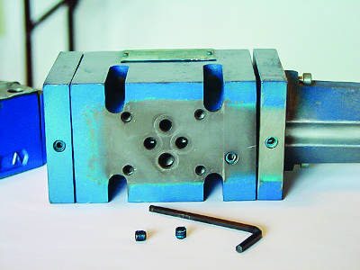
If you and your vendor do not have a valve in stock with the configuration you need, a valve usually can be converted by removing or installing pipe plugs. On the proportional valve used in the examples, the pilot plugs are accessed by taking the pilot valve off the main stage and removing them with an Allen wrench (Figure 5). On some valves, the pilot pressure plug is accessed through the “P” port of the main spool.
Another important thing to remember is that pilot and drain lines and passages are small and can plug. If a new valve is installed and the actuator will not operate, check the pilot and drain passages. This can be done by removing the pilot valve from the main valve’s housing and disconnecting the pilot and drain lines from the manifold. Blow air into the pilot and drain line passages on the manifold. If air comes out the pilot and drain ports on top of the main spool, the passages are clear.
With a greater understanding of how these valves work as well as their proper applications, you should be able to better troubleshoot your hydraulic systems for improved equipment reliability and availability.
