The Importance of Check Valves in Hydraulic Systems
 Check valves are the simplest form of hydraulic devices in that they permit free oil flow in one direction and block oil flow in the opposite direction. Check valves may also be used as a directional or pressure control in a hydraulic system.
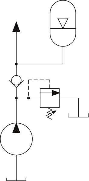
The spring rating varies based on how the valve is used in the system. One of the most common locations for a check valve is immediately downstream of the hydraulic pump (Figure 2). Notice that no spring is shown with the check valve symbol.
 When used in this application, the spring pressure rating is usually 1-5 pounds per square inch (psi) and therefore not shown with the symbol. In this case, the valve is used as a directional control in that it allows oil flow from the pump to the system but blocks flow in the reverse direction. This is commonly called a pump isolation check valve. This valve serves four purposes within the system, which are detailed below:
Block Pressure Spikes
The check valve will block pressure spikes back to the pump. Depending on the pressure, oil flows from the pump to the system at a speed of 15-30 feet per second. When a directional is de-energized to block flow or a cylinder fully strokes, the oil is rapidly deadheaded. The pressure in the line can quickly increase by two to three times. The check valve should then close and block the pressure spikes to the pump.
I recall a plywood plant changing four pumps due to cracking of the pumps’ housings. This occurred over a week’s time on the debarker hydraulics. When the plant ran out of pumps, the staff finally took out the check valve and found that the piston and spring were no longer in the valve.
This $150 check valve cost the company $15,000 in replacement pumps and another $50,000 in machine downtime. That was one expensive check valve. The truth is that if one mechanic had looked at the schematic and known why the check valve was in the system, the replacement of the pumps and subsequent expenses would have been avoided.
Prevent Oil Lines from Draining
When a system is shut down, it is important to maintain oil in the lines. In many cases, the pump is mounted below the level of the system valves, cylinders and motors. The check valve downstream of the pump will prevent the lines from draining once the electric motor is turned off. If the oil in the lines drains through the pump and into the reservoir, a vacuum will occur. Air will be pulled into the lines through the O-rings and seals of the valves and actuators. This can create issues when restarting the system, as the air will need to be bled out.
Block Oil Flow from the Accumulator
 Some systems have a hydraulic accumulator installed downstream of the pump and check valve. When the system is turned off, there is pressurized fluid inside the accumulator. The check valve will block flow from the accumulator, preventing the reverse rotation of the pump.
You can observe the pump shaft or electric motor fan to verify that the check valve is good. Please note that all systems using an accumulator should have a method of bleeding the hydraulic pressure down to zero psi when the system is turned off.
Prevent Oil Flow from the Online Pump to the Offline Pump
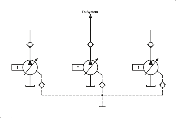
On many systems, one pump is used as a backup or spare (Figure 3). Each pump will have a check valve at the pump outlet port. The check valve will block flow from the online pump to the offline pump, preventing reverse rotation.
I remember being called into a papermill that kept losing one of the two pumps on its chemi-washer drives. The shaft seal of one pump continually blew out. When the mill ran out of spares, personnel had to ship their last pump by air freight to the factory in New York.
The timeline was so critical due to downtime costs that the pump was still warm when they received it back from the factory. Just prior to installing the pump, we removed the check valve in the case drain line and found it stuck in the closed position. This prevented the oil in the pump case from draining, which resulted in blowing out the seal.
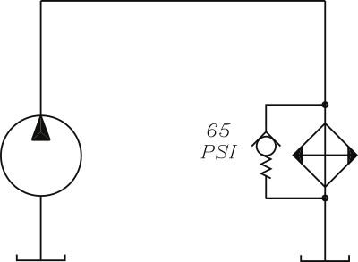
Frequently, a check valve is used for pressure control. A common application is to employ it as a relief valve to protect a heat exchanger (as shown in Figure 4). In this case, the spring rating is usually 65-100 psi.
 If the oil is cold, the inlet pressure to the cooler may reach the check valve’s rating. The check valve will then open and direct the pump volume around the cooler. A check valve will also provide protection for an air-type heat exchanger if the tubes become contaminated.
A few years ago while teaching a class at a sawmill, I observed the students doing their hands-on exercises on the edger. Although a check valve was shown on the schematic to protect the air cooler, the lines to the check valve were plugged off. I asked one of the mechanics about it. He said the check valve was taken off years ago and that they had changed the cooler the week before because of ruptured tubes.
When troubleshooting hydraulic systems, most everyone looks for something large to be the problem, such as a pump, valve or cylinder, but every component has a function. Be sure you understand the purpose of the check valves in your systems.
