What You Should Know About Hydraulic Flow Dividers
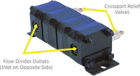 Flow dividers are common components in hydraulic systems. They are used whenever it is important to deliver equal flow to two or more actuators or sets of actuators in a series. There are two types of flow dividers: the motor type and the orifice type. This article will focus on the motor type, as shown on the left.
Motor Type
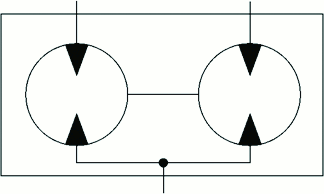
The motor type is comprised of two or more motors (usually gear motors) sharing a shaft. There is a single input shared by the motors and an output for each. The hydraulic symbol can be seen in the illustration below.
If a flow divider has two motors, each of the same displacement, it is called a 50-50 flow divider, as it delivers half the flow that is input out of each motor. However, this type of flow divider can be configured with as many motors as needed, and the displacement of each motor can be different.
For example, if one motor has a displacement that is three times that of the second motor, it would be called a 75-25 flow divider. Any combination may be designed, but the most common are those with motors of equal displacement so the input flow is divided equally between each outlet to the actuators. If the actuators are also of equal displacement, this will ensure they all move at the same speed.
The problem with flow dividers is that even new actuators will bypass different amounts of flow. Regardless of how minuscule this difference in bypassing may be, the actuators can be significantly out of synch after only a small number of machine cycles due to the extreme tightness of the flow divider. This is where adjustments come into play.
 Crossport Relief Valves
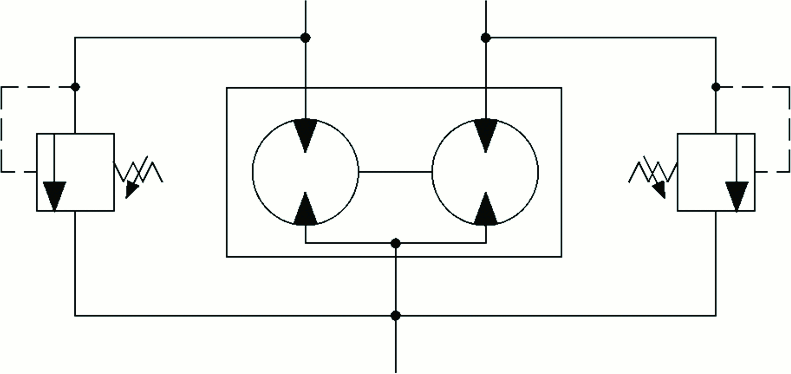
Adjustments are made via crossport relief valves. Many people assume the purpose of these valves is to absorb shock. While they will indeed absorb shock, their primary purpose is to allow some slippage to keep the actuators moving in synch.
When the actuator that is bypassing the least amount reaches its stroke limit, the actuator that is bypassing somewhat more will not be quite at its limit. With the crossport relief valves in place, pressure can build in the line of the actuator that has reached the end of its stroke until the crossport opens. Flow can then continue to the slower actuator and enable it to reach its limit.
A lot of flow dividers come with crossport relief valves built in, but some do not. If the actuators are mechanically connected, it usually is advisable to either purchase a flow divider with built-in crossport relief valves or add a set of crossports to the assembly.
 While speaking at a conference a few years ago, I met a woman from the Department of Transportation. After I had spoken, she introduced herself and said she had attended the conference in hopes of finding someone who could offer some advice on a ferry ramp that had recently been installed. Since my topic included hydraulic troubleshooting, she thought I might be able to assist.
The ferry ramp was a relatively simple hydraulic system but of a rather unique and expensive design. Two enormous cylinders were mounted on the ocean floor to lift and lower the ramp. Since the cylinders had to be installed by divers, each one cost more than $1 million.
After installation, the ferry ramp worked very well. The ramp would lift, the ferry would move under it, and then the ramp would lower onto the ferry so vehicles could be driven aboard. Once the ferry had been loaded, the ramp was lifted, and the ferry proceeded to the island.
After only a couple of months, significant vibration was observed. Before long, the ramp had to be shut down for fear the mechanical infrastructure would be damaged because it was twisting toward one side. Plans were made to replace one of the million-dollar cylinders after only a few months of operation.
 The representative from the Department of Transportation was now asking me whether I had an idea of anything else that could be causing the vibration? I agreed to help and asked if she could provide some schematics of the system. She emailed me a file with the schematic.
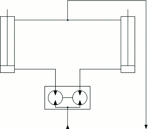
The design was about what I expected. Downstream of the power supply and four-way directional valve, a flow divider and two cylinders were shown, similar to the illustration on the left.
What I did not see on the schematic was a set of crossport relief valves at the flow divider. Often, crossport relief valves, while in place, may not be drawn on the schematic, so I asked her to verify their presence. It turned out the crossports had been omitted from the system, and the small difference in cylinder bypass had rendered them out of synch.
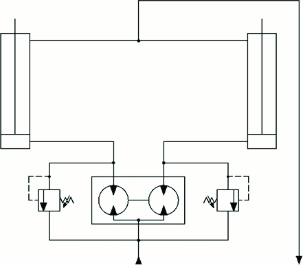 I recommended a set of crossports be installed so when the first cylinder reached the end of its stroke, its associated crossport would open and allow the second cylinder to complete its stroke before stopping the movement of the ramp, as illustrated below.
Once the crossport relief valves were added, the cylinders synched up and all vibration ceased. A million-dollar cylinder replacement was avoided by installing a $200 set of crossports.
Cautions and Recommendations
If crossports are built into the flow divider, they likely will come factory-adjusted. This will work fine for most applications, but they may not be as responsive as you would like. Actuator damage is also possible at high pressures because flow dividers have a tendency to amplify pressure to one side.
Typically, when the flow divider and crossports are part of the original design, their recommended setting will be provided. In the absence of designer specifications, I recommend the crossports be set approximately 200-400 pounds per square inch higher than the pressure required to move the heaviest load at each output of the flow divider.
