Detection Zone Coding for More Efficient Condition Monitoring
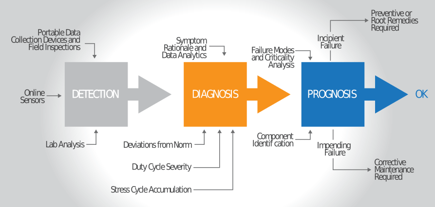
These days, reliability professionals are faced with diverse options related to technologies and methods to detect, troubleshoot and remediate problems. Figure 1 is a simple example of the available options to collect data and arrive at decisions regarding the health of machinery and machine components.
The logical starting point is always to carefully rank failure modes by both criticality and probability of occurrence. For more information on this topic, see my previous column titled “A New Look at Criticality Analysis for Machinery Lubrication.” This method is known as failure modes and effects analysis (FMEA), and has been extensively documented.
 The failure mode ranking sets into motion the critical-path process in reaching optimized decisions related to condition monitoring followed by the prescribed response or remedy. This response should not simply be corrective but also incorporate proactive measures to prevent or restrict recurrence. The emphasis is on optimized decisions and actions.
It’s easy to go cheap (penny wise, pound foolish), but there also can be a temptation at the other extreme (a state of reliability excess), often driven by fear of the unknown. The optimum reference state is an activity of seeking balanced decisions. After all, you are not trying to maximize reliability. There is no greater source to find this balance than knowledge and education.
Detection Zone Table (DZT)
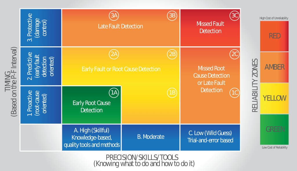
Figure 2 shows a relational table with colours designating condition monitoring detection zones. These zones will be described in more detail later. However, in the simplest terms, they are intended to help focus skills and resources where there is the greatest need. This weighs the benefits of condition monitoring against the inherent costs of the skilful and frequent execution of its application.
In the table, the three columns going from left to right relate to the skills, tools and methods used to perform condition monitoring tasks. The first column is mastery-level condition monitoring and therefore is conducted with precision and expert skill.
The middle column is condition monitoring at a more ordinary or basic skill level. The right column is condition monitoring performed with reckless abandon by untrained and unqualified individuals. At this level, condition monitoring is more wild guesses and dartboard science.
The three columns not only relate to the degree or depth of training and experience but also depend heavily on other factors such as reliability culture, access to technology and tools, and the availability of sufficient condition monitoring staff.
Of these, more than anything else, reliability culture dominates what condition monitoring technicians and analysts do and how they do it. Fix your reliability culture and many other things get fixed concurrently.

The Power of Frequency
The detection zone table also shows three rows that designate the location and timing of the condition monitoring tasks, which are equally important to the outcome. Condition monitoring timing could be continuous (e.g., an online sensor) with little human interaction or periodic using inspection tasks and data collection, such as with portable devices.
The frequency of these tasks has everything to do with the results achieved. Of course, certain machines can do just fine with no condition monitoring at all (run to failure).
Consider the following analogy: Regardless of the fisherman’s expertise, no fish will be caught if his hook is not in the water. The same is true with detecting root causes and active machine faults. Technicians can only detect if they are performing condition monitoring tasks that effectively target known failure modes.
This periodicity is where inspection by a well-trained operator or technician has an advantage over technology-based condition monitoring. For instance, sight-glass oil analysis can be performed daily, unlike laboratory oil analysis, vibration analysis and ultrasound, which often are scheduled at monthly or quarterly intervals.
Condition monitoring is done in near real-time by embedded sensors, a la the industrial internet of things (IIoT), can deliver an equal or superior advantage.
As you might expect, the location has to do with the optimum inspection or data collection point. For example, in oil analysis, where is the optimum location to pull a sample? Likewise, what are the critical examination points when performing inspections? What about the location as it relates to the use of heat guns and infrared thermography?
A long P-F interval is obviously desired, which depends heavily on frequency. This helps close the gap between the point of detection relative to the failure inception point. Using condition monitoring to detect and eradicate failure root causes produces a negative P-F interval.
What could be more ideal? Hence, condition monitoring performed at a high frequency will be more effective and far more proactive (root-cause oriented). This is the strategic foundation of proactive maintenance.

Detection Zone Definitions
The four zones in the DZT are colour-coded as follows:
Green Zone (Proactive): Early root cause detection in this zone is related to frequent inspection in the right places using the right tools and methods as well as expert skills.
Yellow Zone (Predictive): This zone may miss some root causes, but when well-executed, it can detect faults and incipient failure issues early (near to the time of inception). It will depend on frequent inspection coupled with skilful techniques and effective tools.
Amber Zone (Protective): Condition monitoring in this zone catches faults before catastrophic failure and collateral damage can occur. Some may call this just-in-time condition monitoring, but for many reasons, it is a slippery slope at best. Although a pre-failure detection may be possible, in other cases the failure development period may be too narrow for a practical forewarning to be achieved. Of course, there are also those pesky sudden-death failures.
Red Zone (Breakdown): This is the complete operational failure.
Detection Zone Coding
Next, assign failure modes to the optimum, best-fit detection zones. Start by working down the failure mode ranking, beginning with process-critical machines. Place each failure mode in one or two zones within the DZT.
Highly ranked failure modes should be assigned to the green zone. Others may fit within the yellow zone. Lesser-ranked failure modes can be placed in the yellow or amber zones.
Let’s apply this to a hypothetical example. A high-speed centrifugal compressor has had chronic problems with bearing failures. An FMEA exercise ranked varnish and sludge to be the apparent root cause in most cases.
The primary root cause was impaired lubricant air-release issues, which was made worse by entrained air sources. Adiabatic compressive heat from the entrained air was the cause of varnish.
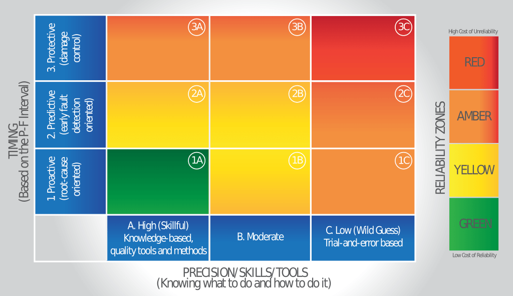
Figure 3 recasts the DZT to illustrate how condition monitoring can detect and respond to this type of failure in different ways. The varnish example was used because I’ve seen the actions and results listed within the table’s cells in many real-world cases. Following is a brief description of each of the cells.
Cell 1A: Skillful and frequent inspection and oil analysis detect and recognize the aeration problem. The root causes (air induction and cross-contaminated oil) were eradicated.
Cells 2A and 3A: The main difference here is the delayed detection and response to aeration and the need to address the varnish problem that ensued. Early detection prevents varnish. Late detection requires de-varnishing of the oil and machine. This leads to extra costs and extra risk.
Cell 1B: Here, a lack of training on varnish and aeration resulted in treating the symptom (degas) and not the root cause (the source of air-release and entrainment problems).
Cells 2B and 3B: With the aeration problem undetected and unfixed, the aeration issue quickly escalates into a varnish and sludge problem. Removing the varnish and sludge followed by changing the oil is nothing but a short-term remedy. The root cause remains unchecked, so aeration and varnish will soon return.
Cell 1C: While aeration was detected, the haphazard solution of changing the oil and filter did nothing to provide a real solution. How many times do you need to change oil to fix an air-entrainment problem?
Cell 2C: The time delay and poor condition monitoring skills lead to advanced varnish being detected but not the root cause. Once heavy varnish potential is present, the compressor’s days are numbered.
Cell 3C: A bearing failure and teardown revealed oil-way sludge and restricted oil flow to the bearing (starvation). The maintenance staff immediately declare the oil was defective and the cause of the bearing failure. The oil supplier was fired, and new oil was put into service. Will the second oil supplier be fired soon, too?

The Critical Five
Is it necessary for a person to use the DZT for optimized condition monitoring? Absolutely not. However, the table helps you understand the consequences of shoddy condition monitoring. As I’ve seen for years, just any oil analysis program is not good enough. The same is true with inspection and the many other condition monitoring technologies and methods. Doing versus doing well can produce sharply different results.
Think of the critical five as a simple way to define what is meant by “doing condition monitoring well.” They are as follows:
The What - Know what you are trying to detect or analyze. Is it a symptom or a root cause? Is it measurable or verifiable? Is it controllable?
The Why - Know why it is important. How does it affect reliability and asset availability? How does detecting and controlling it reduce the life-cycle costs, energy consumption and environmental impact? How does it increase safety?
The Where - Where is the most effective location to find what you are trying to detect? How can this location be improved and made more convenient (installing inspection windows, for instance)?
The How - What skills, methods and tools will be needed for optimized detection and control? How can root causes be detected before the onset of failure? How can failure symptoms be detected early to extend the P-F interval and make remediation convenient without significant loss of the remaining useful life (RUL)?
The When - When must condition monitoring tasks be performed to achieve the reliability objectives? How can daily inspections and online monitoring play an effective role?
Condition monitoring is like a treasure hunt. The greater fun is in the search. And yes, there is a treasure at the end.
