Circulating Oil Systems: What You Should Know
Circulating oil systems or lube skids provide a continuous flow of lubricant to bearings, gearboxes and blowers. They lubricate machinery used to pump stormwater, circulate fresh air into mines, extract oil, power ships, manufacture paper and chemicals, and test military equipment.
In some cases, the bearing manufacturer supplies the lube skid as part of a single-source solution. In other instances, a bearing already in service may be overheating or exhibiting wear and is in need of a more dynamic lube system. In either case, the responsibility for speccing the oil system lies with the party having firsthand knowledge about the bearing. The circulating oil system may be less familiar territory.
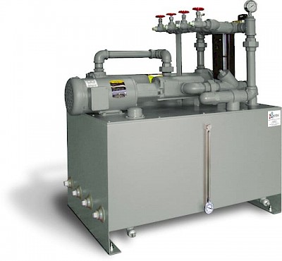
There are three approaches to procuring a circulating oil system. The first is to construct it with in-house resources. This is both a science and an art. There are many skilled maintenance individuals who can make the connections, assemble the piping and get all the controls to work together. Be prepared to spend time researching components and suppliers. If working without a drawing, you can expect on-the-spot engineering and re-engineering (i.e., fixing mistakes and miscalculations).
The second approach is to purchase a prefabricated unit. Some manufacturers of circulating oil systems have off-the-shelf units. They may be completely assembled or can be quickly constructed from on-hand components. The shortened lead time can be helpful when dealing with a bearing that is overheating in summer temperatures. There will be limited options to choose from, which could result in an underequipped system or an oversized, less efficient system.
The third approach is to design a system with a specialized manufacturer. There are inherent benefits to experience and planning. A good manufacturer will offer drafting/engineering resources, have reliable suppliers and be an expert troubleshooter. Circulating oil systems often provide decades of service, so it is best to design them to have adequate controls, convenient maintenance and efficient power usage.
No matter which approach is employed, forethought should be given to what the system needs to do and how an array of different parts must come together to accomplish it.
The Essential Function: Oil Flow
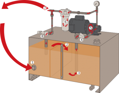
The essential function of a circulating system is to deliver the prescribed flow of oil into the bearing. The oil is collected from the bearing, as suggested by the name “circulating oil system.” The oil is filtered and cooled (if necessary) while passing through the lubrication system. The path the oil follows is shown in Figure 2. It begins with the oil coming into the reservoir through piping connected to an overflow port at the bearing.
The bearing is located at a higher elevation than the system, so the oil flows by gravity. Fluid spills over the baffle in the reservoir. Larger contaminants tend to settle on the side of the baffle where the oil enters. The suction created by the pump draws the fluid into the piping. A strainer traps large particles before the oil enters the pump. The motor drives the pump to create flow and pressure. Next, the oil is routed through a filter to remove fine particles so they do not reach the bearing. The oil then flows to the bearing. Finally, excess fluid is directed back into the reservoir through a bypass valve.
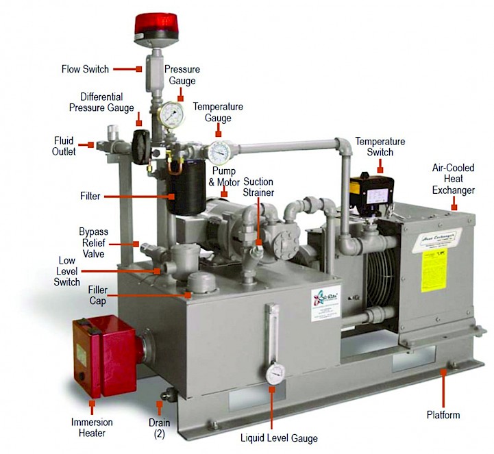
In its simplest form, a circulating oil system may not require any type of control other than its power supply. The system forms a loop and functions without interruption until a filter replacement is necessary. The features inherent to a circulating oil system are shown in Figure 3.
Determining System Requirements
Each application of a circulating system is unique. The bearing manufacturer should be consulted for the specific flow rate, system pressure, fluid type and operating temperature. The user specifies the connecting piping size, line distances, elevation to the bearing, surrounding temperature, power availability and safety considerations.
Instruments and electronic controls can be added to cope with demanding environments or provide active feedback to the operator. For instance, warnings and fail-safes can ensure that any variances are detected and action is taken before the lubrication of the bearing is compromised.
Such precautions may be warranted if the bearing is started and stopped as part of its normal operation, the load or rotation speed varies, the temperature fluctuates, or it is in a particularly dirty environment.
Some bearings must operate without interruption, which requires that the circulating oil system do the same. Redundancy can be built into the system. Dual filters with separate piping and control valves enable the filter to be changed while the flow of oil is diverted. A built-in second pump and motor can serve as a backup so the system remains operational during service or major component replacement.
Matching Components to the Requirements
Consider the following factors when specifying a circulating oil system:
Flow Rate
If the system is supplying more than one bearing, the flow rate must equal the sum of the requirements. Flow into the bearing is controlled through the use of a needle valve at the delivery point. The pump and motor are sized to the maximum required flow rate plus a small contingency factor. The pump supplies oil at a constant rate. Any flow in excess of what the bearing can accept is diverted back into the lube skid’s reservoir by a bypass relief valve located near the fluid outlet.
Pressure
Typical operating pressure is 35 pounds per square inch (psi) or less. Specialized applications may require higher pressures, such as a system designed to suspend a bearing in lubricant during startup to avoid metal-to-metal contact. The maximum amount of pressure is determined primarily by the pump’s capability. Adjusting the bypass relief valve so less oil passes through to the bearing will increase system pressure.
Pumps and Motors
Motors are available in different voltages, frequencies and phases to best suit the available power sources. The typical motor is rated as TEFC (totally enclosed, fan-cooled) and is suitable for many industrial environments. A system located in an area with combustible vapours and dust may need to be rated as explosion-proof. The class, division and group must be identified for an explosion-proof motor.
Filtration
A circulating oil system typically uses three methods of filtration. The reservoir is equipped with a baffle that partially separates the two sides. The fluid comes into the reservoir on one side of the baffle where sediment tends to settle. The oil passing over the top of the baffle benefits from this initial phase of passive filtration. As the fluid is drawn out of the reservoir, the second level of filtration is achieved when it passes through a mesh strainer. Final filtration occurs prior to the fluid exiting the system, usually with something like a 23-micron filter. It is advisable to clean the strainer and change the filter on a regular maintenance schedule.
Gauges
The gauges on a circulating oil system offer a means of monitoring the operating conditions. A pressure gauge between the pump and bypass relief valve is used to verify that the pump is operating as intended and that the bypass relief valve is preventing excessive pressure buildup. The temperature of the fluid in the tank is visible using a thermometer built into the liquid-level gauge.
A temperature gauge installed in the piping gives feedback on the temperature of the fluid after passing through a heat exchanger. A differential pressure gauge is used to measure the amount of pressure lost while passing through the filter. Loss of pressure indicates the filter may need replacing.
Switches
Signals obtained from switches can be interpreted by electronic controls to send information to monitoring stations, manage how the unit functions, activate alarms or shut down equipment.
A temperature switch provides the ability to signal a high temperature or activate the heat exchanger. A liquid-level switch can indicate that the oil level in the tank is low because of system loss or because fluid is not returning fast enough from the bearing. A liquid-level switch can also be used to signal when the tank level is high due to an unexpected restriction of flow in the piping or at the bearing.
A low-flow switch activates when flow drops below the desired level. This condition can be caused by a clogged filter, pump malfunction, power interruption or depleted fluid. The signal from the switch can give valuable warning time to take corrective measures.
A differential pressure switch signals that the pressure is elevated after passing through the filter. This indicates the filter needs to be replaced.
Heat Exchangers
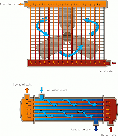
The purpose of a heat exchanger is to reduce the temperature of the oil before returning it to the bearing. Heat exchangers transfer heat from the fluid to either the air or to water (Figure 4). An air-cooled heat exchanger uses a fan to blow air over the oil as it passes through a series of smaller tubes. The tubing for a water-cooled heat exchanger is routed through a cylinder that has a continuous supply of water passing through it.
The heat exchanger is sized to the number of British thermal units (BTUs) required to be removed per hour. This is calculated using the temperature of the oil as it exits the bearing and the temperature required when returning to the bearing. The heat exchanger size is dependent on the air or water available for cooling.
An air-cooled heat exchanger cannot reduce the oil temperature to less than the surrounding air temperature. Warmer ambient temperatures will create the need for a larger heat exchanger. A water-cooled heat exchanger offers increased efficiency with a lower water temperature and a higher flow rate of water.
Heat exchangers can be manually operated by an attendant or controlled automatically using a temperature switch or readings from a temperature gauge. They can also be wired to operate continuously.
Immersion Heaters
An immersion heater works in contact with the oil in the system reservoir. It raises the temperature of the fluid. A typical use would be to start up the system in cold climates. The oil is heated to reach its optimal viscosity before circulating to the bearing. The heater uses a built-in thermostat to shut off when the predetermined temperature is achieved.
Installation Environment
The operation of a circulating oil system can be affected by its surroundings. Temperature, altitude and exposure to the elements should be taken into consideration in the design. The space available for the unit affects the proportions of the tank, the mounted position of the components and the piping configuration.
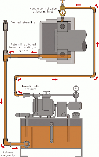
The bearing should be at an elevation higher than the circulating oil system so the oil can return to the system by gravity (Figure 5). The return line must be vented and two sizes larger than the supply line to avoid backup. The pressure required to supply oil to the bearing can be affected by the elevation to the bearing, reductions in pipe size and any restrictions caused by manifolds or nozzles.
Reservoirs and Piping
A standard reservoir is welded steel. The cover is heavy-gauge steel. It is used as a platform for mounting system components. The piping and fittings usually are made of iron with national pipe thread (NPT) fittings. The entire system requires painting or some type of protective coating to avoid corrosion.
Reservoirs and piping can also be stainless steel. The connections may be welded, and some fittings are flanged. Circulating oil systems should be tested for leak detection and component operation before being put into service.
Getting What You Ask For
There is no one size that fits all when it comes to circulating oil systems. Work closely with the bearing manufacturer to determine optimal operating conditions. Tell your lube skid builder what you need the system to do. Factor into the design the fail-safes, maintenance and durability that suit your application. The system will be as good as the forethought put into it.
