Why Equipment Fails and What You Can Do to Prevent It
Unplanned repairs and unplanned downtime are ten times more expensive than planned repairs and planned downtime. In addition to being expensive, unplanned downtime is unproductive, disruptive, distracting and sometimes causes collateral damage. Planned is manageable; unplanned is not.
Planning repairs to equipment require advance notice months before critical components fail. To this end, one must understand the following:
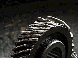 Why do equipment components fail?
- What are likely failure mechanisms for those components?
- What are the factors that initiate and accelerate the failure mechanisms?
- What are factors that mitigate or avoid the failure mechanisms?
- What proactive condition monitoring methods can identify contributing factors that accelerate failure mechanisms?
- What predictive condition monitoring methods can measure failure progression from incipient to catastrophic?
Failure Mechanisms
Abrasion, adhesion, fatigue, electric discharge, corrosion and deposition are common failure mechanisms from the referenced literature. Characteristics of these failure mechanisms are listed in Table 1 and described below.
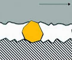 Abrasion affects nearly all mechanical systems. It begins when silica dust particles are transported by the lubricant to a narrow clearance between moving surfaces. Hard particles that are too large to pass through become embedded into one surface and cut the other. The shear force between the lubricated hard particles and the moving surface cut a V-notch into the moving metal surface.
This cutting process emits a spectrum of mechanical vibration from the point of abrasion and generates abrasive wear debris, which is carried away by the lubricant. This mechanism generally is not self-propagating and is easily offset by contamination control. It can be triggered by a surge in the circulating system or by a defective breather.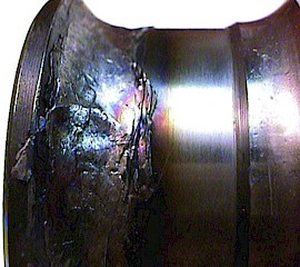
Adhesion (or boundary wear) impacts nearly all mechanical systems with loaded components. Adhesive wear and other boundary wear damage is progressive and self-propagating while also accelerating corrosion. Metal-to-metal contact occurs when the lubricant film (designed to eliminate friction and separate a roller from a race or a journal from a shaft) fails due to inadequate lubrication. The increase in friction and shear causes mixed and boundary lubrication regimes.
| Failure Mechanism | Affecting Components | Contributing Factors | Mitigating Factors |
|---|---|---|---|
| Abrasion | Mechanical | Dust contamination, System Sure, Defective breather | Contamination control, clean, dry, fit for use |
| Adhesion | Mechanical | Lubricant misapplication, slow speed, excess load, low viscosity | Lubrication, speed, load, viscosity |
| Fatigue | Rotating, vibrating, flexing | Elevated dynamic loading | Minimize dynamic loading |
| Rolling Fatigue | Bearings, gears | High dynamic load improper fit | Minimize dynamic loading |
| Bending Fatigue | Shafts, joints, fasteners, structures | Sharp fillet or other tensile stress concentration | Pre-stressed compression, fracture-toughness, fillet radius |
| Cavitation Fatigue | Impellers, pumps, valves, piping | Speed, pressure, and flow extremes | Speed control, fluid dynamics, and surface treatment |
| Electric Discharge | Mechanical, electrical, inductive, static | Shaft currents, moisture, round faults, deterioration, looseness, corrosion | Grounding, contamination control clean, dry, fit for use |
| Corrosion | Mechanical, electrical | Water or other corrosive contamination non-desiccating breather | Contamination control, clean, dry, fit for use |
| Stress Corrosion | Shafts, joints, fasteners, structures | Sharp fillet or other tensile stress concentration | Pre-stressed compression, surface seal, fracture-toughness, fillet radius |
| Galvanic Corrosion | Structures, fasteners, electrical and mechanical | Electrolyte between dissimilar metals such as carbon and stainless steel | Insulate between dissimilar metals |
| Erosion Corrosion | Impellers, pumps, valves, piping | Corrosive fluid with eroding flow | Seal/protect surfaces |
| Deposition | Flow controls, filters, screens, valves, fans | Temperature cycles, polar constituents, static charge | Awareness & prevention |
The contact emits stress waves. Compression with mixed and boundary lubrication leads to shear and friction, which results in intense heating, melting and discolouration. Metal debris and oxides are released into the lubricant, and a spectrum of vibration is emitted. This mechanism can be prevented by maintaining the proper lubricant at the correct level and by operating at the designed speed and load. It may be triggered by a slow speed, high load, low viscosity or inadequate lubricant delivery.
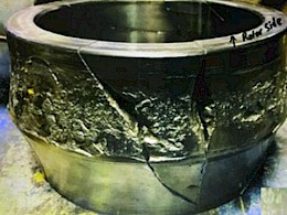 Rolling Fatigue (also called Hertzian fatigue) affects mechanical systems with loaded bearings and gears. Roller bearings and gears often fail due to the process of rolling contact, which eventually leads to material fatigue cracks and spalling. Compression between the rollers and races and between gear teeth produces subsurface Hertzian contact shear that eventually work-hardens the metal until microcracks form, grow, interconnect and then release metal debris. Rolling impacts at spall and other surface defects magnify stress waves and release more debris into the lubricant. Fatigue can be offset by minimizing dynamic loading from imbalance, misalignment and resonance, as well as by static load reduction and other maintenance practices; it can be triggered by an improper fit or thermal growth.
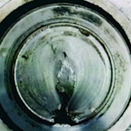 Bending Fatigue affects shafts, joints, fasteners and structures. Cyclic bending produces fatigue cracks originating from surface defects in the vicinity of tensile stress concentrations.
Contributing factors include sharp fillet radius, material flaws and geometric stress concentration sites. Mitigating factors may include pre-stressed compression, use of materials with high fracture toughness and smooth fillet radius.
Cavitation Fatigue failure mechanisms typically occur on impellers, pumps, valves and other flow devices. Cavitation fatigue involves cyclic void collapse shock waves that cause sub-surface fatigue cracking, pitting and spalling. Contributing factors include extreme variations in speed, pressure and flow. Mitigating factors include speed control, fluid dynamics and surface treatments.
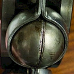 Liquid cavitation is stimulated by pressure variations in the cyclic fluid flow near the surface. In a slow part of the pressure cycle, suction enables evacuated micelle nucleation originating from solid surface irregularities.
Highly saturated dissolved gas from the surrounding liquid may diffuse into expanding bubbles. Later in the pressure cycle, suction is released, and the bubbles implode back toward the nucleation surface irregularities. The implosion causes a supersonic surface impulse and transfers compression and shear stress waves. Shear from the stress wave dislocates subsurface material morphology. Eventually, these dislocations lead to fatigue cracks and spalling.
Note that when the bubbles contain partial pressure gases diffused from the surrounding liquid, there is also intense heating from the compressed gases. Cavitation damage, which normally is progressive and self-propagating, often results in fatigue cracking and stress corrosion cracking. It is triggered by pressure, flow and speed variation but can be offset by fluid flow design, control, speed and surface treatment.
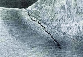 Erosion can affect valves, pipes, baffles, impellers and other electrical and mechanical components exposed to streaming particulate matter. It occurs when high-velocity liquid or solid matter impacts a solid surface, causing intense points of compression and resulting in deformation and shear. Stress waves are emitted from the impact points, and debris is dislodged from the damaged surface. This failure mechanism can be prevented by protecting surfaces with energy-absorbing coatings.
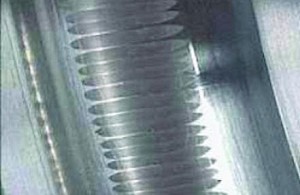 Electric discharge affects electrical components and inductive or static charged mechanical components with voltage. The potential to ground applies an electric field through a medium. Electrons and ions accelerate via spark, track, and arc plasma.
Arc-spark events yield a wide spectrum of mechanical and electrical energy. Surface morphologies undergo surface erosion leading to heat damage. An electric discharge ionizes proximate matter to form a discharge or plasma track.
Contributing factors include moisture, degraded insulation, ground faults, looseness, corroded contacts and contamination. Mitigating factors include clean and dry materials and compartments.
Corrosion impacts almost all electrical and mechanical systems and is synergistic with all other failure mechanisms. It occurs when a corrosive substance attacks metal and changes the surface from strong, thermally and electrically conductive metal into soft, electrically and thermally resistive oxide.
The resulting oxide is easily rubbed off by shear, which exposes fresh metal for sustained oxidation. Mild rubbing emits stress waves and spreads soft metal oxides into the lubricant, exposing the metal to the oxidation process. This mechanism may be prevented by moisture contamination control. It can be triggered by process contamination, a coolant leak or a defective desiccant breather.
Three synergistic combinations of corrosion with tensile stress, galvanic current and erosion are identified below.
Stress corrosion affects shafts, joints, fasteners and structures. This synergistic combination of tensile stress and corrosion produces intergranular corrosion accompanied by tensile fracturing, which progressively self-propagates.
Contributing factors include sharp fillet radius, corrosive substance and stress concentration. Mitigating factors include pre-stressed compression, surface sealing and material fracture toughness.
| Measurement Method | Proactive Detect Root Cause | Predictive Quantify Failure in Progress |
|---|---|---|
| Vibration | Balancing Alignment | Roller/gear defects Failure progression |
| Oil | Contamination control Adequate lubrication | Ferrous debris Particle shape classification |
| Thermal | Normal lines Normal connects | Electrical faults Mechanical adhesion |
| Motion | Acceptable resonance Acceptable timing | Synchronous resonance Timing faults |
| Spark | Survey motor shaft brushes Survey before entry | Low voltage spark events High voltage are events |
| Inspect | Preventive maintenance Quality control | Substance deposition Procedure misapplication |

Galvanic corrosion affects structures, fasteners, and electrical and mechanical components. This occurs when an electrochemical corrosion corrosive substance couples a noble cathode, such as stainless steel, with a less noble anode, such as carbon steel.
Contributing factors include the presence of corrosive substances together with the electrical connection of more noble with less noble metals. Mitigating factors include insulating interfaces between dissimilar metals, protecting/coating/sealing surfaces, contamination control and visual inspection.
Erosion corrosion is an erosion process accompanied by a corrosive substance. Erosion removes oxidized surface material, exposing underlying metal for rapid and sustained oxidation. It affects impellers, pumps, valves and piping.
Contributing factors include corrosive fluid with eroding flow. Mitigating factors include providing surface protection or sealing.
Deposition results from a dysfunctional and progressive accumulation of foreign material on a critical electrical or mechanical component. Examples include precipitated varnish formation and accumulation on a control valve, fibrous material accumulation on a fan and polar substance accumulation on an electrical circuit.
Varnish accumulation on a control valve may lead to plugging and sticking, while fibrous material accumulations on a fan may cause imbalance and a potential fire risk. This failure mechanism can be prevented by detecting, interpreting and addressing the specific accumulation process. The corrective action plan should be specific to its characteristic process.
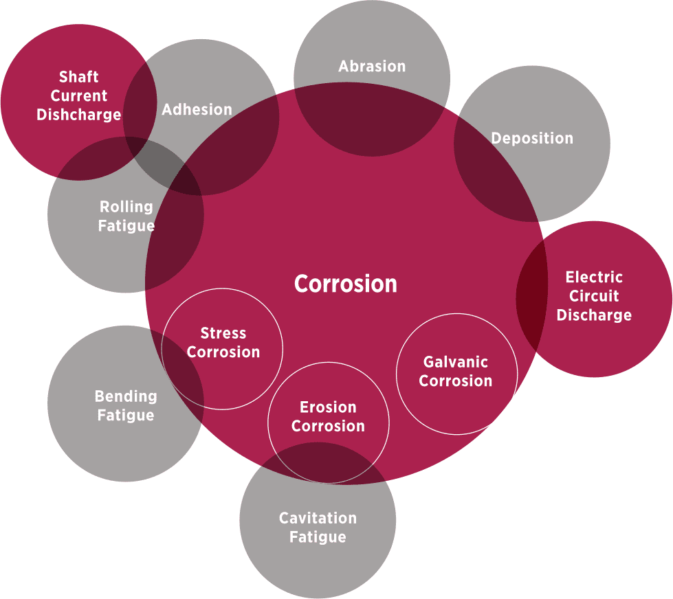
Interaction of corrosion and/or electric discharge mechanisms with the other failure mechanisms described above is synergistic, as portrayed in the Venn diagram in Figure 1.
Time-to-fail accelerates with interacting factors. Remaining useful life, e.g., incipient to catastrophic failure, shorten from decades to years, and even to months under these combined effects.
Corrosion and electric discharge deteriorate surface morphology and destroy the remaining useful life. Corrosion contributes to mechanisms of electric circuit discharge, deposition, abrasion, adhesion, rolling fatigue, bending fatigue and cavitation fatigue. Stress corrosion, erosion corrosion and galvanic corrosion mechanisms advance general corrosion rates by orders of magnitude. Electric discharge erosion reduces the capacity for surface metals to resist pitting from rolling fatigue.
Condition Monitoring
Table 2 updates the table from the March 2003 Machinery Lubrication article, “How Machinery Wear Rates Impact Maintenance Priorities.” This revised table demonstrates how vibration analysis, oil analysis, thermography, motion amplification, spark detection and visual inspection are complementary techniques to proactively evaluate root cause issues and predictively quantify failure mechanisms in progress.
Vibration monitoring and analysis employ a measurement configuration (maximum frequency of interest, sonic and ultrasonic frequency stress wave and heterodyne ultrasonic) appropriate for detecting and trending desired measurement information.
Machine vibration monitoring is often the core condition-based monitoring methodology for drives and driven rotating machinery. Proactive measurement of sinusoidal mechanical vibrations quantifies troublesome root cause issues such as misalignment, imbalance, looseness, and resonance and facilitates early detection and correction. Sonic and ultrasonic frequency range impact monitoring measures the progression of roller and gear defects. This predictive information is helpful to identify failing components, evaluate severity and schedule planned maintenance.
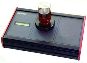 Oil analysis includes sampling in-service lubricants and testing those samples to evaluate fluid chemistry, system contamination and machinery wear. Proactive monitoring for fluid condition and system contamination supports precision lubrication practices. Predictive monitoring for ferrous and nonferrous wear debris, together with particle shape classification, is helpful to identify failure mechanisms, evaluate severity and schedule planned maintenance. Oil and vibration analysis together are complementary, not redundant.
Thermal monitoring and analysis include single point, line-scanning and thermal imaging measurements. Proactive temperature scans are simple, quick and highly effective - finding something hot or cold that should not be, in comparison with surroundings or with similar mechanical and electrical components. Thermal images superimposed on respective visual images facilitate recognition, identification and reporting of possible problems. Thermal monitoring is often the best condition monitoring technology to identify and predict potential failure points for electric power connection, transmission and distribution systems.
 Motion monitoring and analysis include motion amplification, phase analysis, frequency analysis and amplitude analysis using video camera imaging. Proactive uses of motion amplification include monitoring and accepting structural resonance, mechanical timing and synchronous phasing. Motion monitoring, like thermal imaging, takes in thousands of measurements within a field of view for quick identification and severity determination using non-intrusive surveillance. Problems with amplitude, timing and phase are observed, amplified and trended.
Spark monitoring and analysis include distinguishing and analyzing radio waves produced from arcs or sparks. Proactive uses of spark detection and analysis include a survey of motor bearings and a survey before opening an electrical enclosure. Predictive uses of spark detection and analysis include trending low voltage spark events and/or high voltage (>1000 V) arc events.
Inspection and test include visual inspection with or without tools. Visual inspection is typically performed during walk-around vibration, oil, thermal, motion and spark monitoring, as well as during preventive and quality control procedures. These inspections proactively find and correct misapplication, contamination and incorrect adjustments. They predictively identify failure progressions such as substance deposition or procedure misapplication.
Case Histories From A Mill
The mill has decades of experience with vibration analysis, oil analysis and lubrication. Team members are skilled and have very good tools, and the mill operates with about 97% availability.
Root Cause Failure Analysis (RCFA) reports included failed rolls, couplings, seals, bearings, forming wire, cooling tower, driveshafts, nozzle, screen, gears, retainers, switch and belt drives.
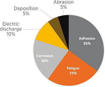
This figure represents failure mechanisms as a percentage of estimated RCFA production and RCFA estimated repair costs:
- Adhesion 35%
- Fatigue 25%
- Corrosion 20%
- Electric discharge 10%
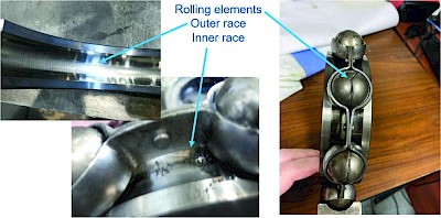
The photograph in Figure 2 shows the shaft current electric discharge failure of a 600 HP motor bearing.
Continuous Improvement
Continuous Improvement based on facts, such as Root Cause Failure Analysis (RCFA) of planned and unplanned repairs, provides an opportunity for cost reduction and reliability improvement. The next step for continuous improvement based on RCFA history may call for expanding an ongoing condition monitoring to cover all the above-listed methodologies. Add the new condition monitoring methods, starting small; demonstrate success and grow to achieve desired continuous improvement objectives.
For example, continuous improvement to start-small-and-grow an active vibration analysis, thermography, motion amplification and preventive inspection condition monitoring program requires the addition of oil analysis and spark detection.
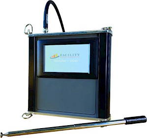 Start-Small- And-Grow Spark Detection
If RCFAs indicate issues with electric discharge causing damage to DC motor drives or other equipment, consider start-small-and-grow by using arc-spark measurement. For example, a Spark Data Collector with a radio wave sensory antenna uses peak-to-peak stress wave analysis to reveal spark events. Use this device to survey and locate faults. Follow up with periodic measurements to monitor, trend and gauge severity.
Conclusion
Common failure mechanisms include abrasion, adhesion, fatigue, electric discharge, corrosion and deposition. Mechanisms often progress in stages from incipient to catastrophic, to which component types each applies, factors that contribute and other factors that mitigate each mechanism.
Rapid equipment failure occurs when galvanic corrosion, stress corrosion, erosion corrosion and electric discharge mechanisms denigrate surface morphology, synergistically accelerating progression from incipient to catastrophic under sustained effects of fatigue and adhesion mechanisms.
Proactive and predictive condition monitoring methods, including vibration, oil, thermal, motion, spark, and inspection are recommended to detect the root cause contributing factors and to measure various stages of progressive failure. For example, the start-small-and-grow condition monitoring program already covering vibration, thermal, motion and inspection by adding on-site oil analysis with wear debris analysis and adding spark detection.
