Why the Oil In Your Air Compressor Matters
Air compressors are the main component of compressed air systems, which are an essential part of any modern industrial plant. After the air is compressed, it becomes a safe and abundant source of energy. Because of this, compressed air has been a necessary part of industrial processes for decades.
The most common air compressor design used across industries today is the screw compressor. This is because they are efficient, widely available, and come in a variety of sizes from 10 HP all the way up to 500 HP. Standard two-stage designs can also operate at up to 13 bars (188 psi) of pressure.

Troubleshooting challenges is an essential skill for any team tasked with keeping machinery running. Our team has spent years helping plants improve their processes and conquer challenges. During that time, we refined our reliability and data analysis techniques. Since today’s reliability programs often rely heavily on data and analytics, I will be sharing some figures about the amount of downtime associated with one of the smallest footprints inside a plant: the humble air compressor.
In general, the compressed air station will usually around remove 1.2-5% of the total cost of a plant’s rotating assets. However, it can be up to 20% for general utilities and it can be up to 80% for industries like spinning and weaving, where it is necessary for the majority of production activity.
While the extent to which individual industries rely on compressed air will vary, most industries require compressed air for some part of their process and all will suffer from various levels of downtime if compressed air becomes unavailable or has its quality compromised. For example, 46-86% of downtime in industries like Fast Moving Consumer Goods (FMCG), assembly-based processes, spinning and weaving, and steel plants can be attributed to compressed air. This downtime is a direct production loss everyone would like to avoid. This can usually be done by employing redundancy, but that strategy can only go so far.
Compressed Air Maintenance Strategy
The first thing on the mind of any management team considering compressor improvements should be mitigating the risk of downtime associated with compressed air. As I mentioned, redundancy is often the first strategy employed here, and this often makes sense – to a point. But buying backup compressors is not the only solution to the problem, nor does it always make financial sense to do so. On top of that, many OEMs and utility teams spend unnecessary capital employing Preventive Maintenance on these assets, rather than using a more focused strategy.
The utility manager of a plant once asked me what he would save by discovering potential compressor failure earlier. He was currently buying a new compressor every year even though no production capacity was being added and no old compressors were salvaged.
In order to answer his question, we need to go back to the basics of proper compressor maintenance and failure risk mitigation. Let’s look at a case study to better understand these principles.

Case Study
In a modern, up-to-date steel plant the compressed air station was designed for 25% redundancy in order to ensure the maintainability of the plant, which is the time needed to get the assets back into production. Production could easily continue with three out of four compressors, giving the needed flexibility to the maintenance and supporting OEM teams to perform the scheduled preventive maintenance activities without impacting production. All seemed good and risk was mitigated.
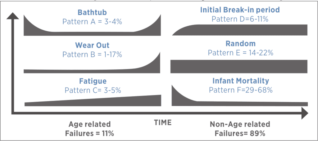
For now, we’ll disregard the high cost of spare parts and the three holding capacities – we’ll discuss those later. The primary flaw of this type of maintenance plan is that it was purely time-based and didn’t consider the possibility of “random” failures. Random failures are not usually that random; they happen mainly due to human error. We refer to them as random because their occurrence on a failure pattern curve is random. They are the flat part of the curve which illustrates the actual useful life of the asset (in our case, the compressor).
Luckily the plant was doing condition monitoring (CM) with the OEM to measure vibration and thermography, along with oil analysis when it was needed.
Their CM techniques and strategy were built on the P-F Curve and the ability of the measurements that were gathered to help them intercept failures early or at their inception. The most understood and widespread CM technique used in P-F Curve analysis is vibration, while the oldest is oil analysis.
The most challenging part of using a P-F Curve is actually getting the curve of the failure mode correct, based on accurate time frames between every stage of the failure (x-axis is time).

The most important consideration here is determining how failures actually happen. It’s been well documented that random failures account for the majority of what we see in the industry. It’s also regrettably common for people to underestimate how fast the faults can develop given the particular circumstances.
In the case of our steel plant, we will observe an accelerated failure that consumed 68% of the life of the bearings in the air end of a compressor before anyone detected the potential failure. Failing to detect this problem resulted in the bearing enduring the equivalent of 16000 hours of operation in just 18 days (432 hours).
Screw Compressor Construction
In order to perform reliability analysis for any assets you have to understand the operational context of the machine, how it works, what components have the highest risk of failure, and what failure mode would impact the machine’s reliability the most.
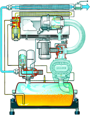
The machine in Figure 3 is an oil-flooded screw compressor, also known as an oil-injected screw compressor. It has an air end driven by an electric motor and uses the pressure generated by the air end to drive the oil in the lubrication circuit through the lubricated components as well as the filtration and cooling systems.
As you can see, the air enters the system through an air filter where the majority of destructive particle contamination should be captured. The oil and air are mixed upon entry on the top of the bearings and the air end begins compressing this mixture. After passing through the air end the temperature increases significantly, averaging between 73°-83°C, which is considered normal for this type of machine. The oil then drops into the settling tank by gravity and the compressed air leaves through the oil air separator, at which point it is cooled in the aftercooler and leaves the compressor for further treatment. The oil takes a different path out through the filter and then the thermostatic valve on its way back to the air end.
How To Kill Your Bearings Quickly

The oil in our machines is a very critical asset. We must ensure that not only will it perform, but it will also protect the bearings from excessive or sudden wear.
If you look closely at Figure 3, you will notice a hose providing the entry of ambient air after the filter. This is a weak point for this compressor that could initiate many failures if the maintenance team doesn’t understand its failure modes or what to look for when they inspect the machines.
In our case study, a small crack in the plastic hose occurred after the air filter due to the wear and tear of the process. If you suspected that this crack was premature, you would be right. An incorrect control setup had been put in place which manipulated pressures in the hose. This was done in order to accommodate requests from operations to avoid low pressures in the production line. The frequency with which the machine cycled between loading and idling was too rapid. This cycling is something that is counted by any modern compressor controller since it is one of the primary root causes of many compressor failures. Once this hose cracked, it presented a golden opportunity for abundant and destructive contaminants like silica dust to enter the system.
Damage like this is an open invitation for dust particles of all sizes to enter at the worst possible location, bypassing the filter and landing directly on the defenceless bearings. What happened after that was predictable: the next vibration analysis indicated the bearings were failing.
An Upset Utility Team
Denial is typical human behaviour when we get news that we don’t like. We try to find an alternative reality that disregards the inconvenient truths we’ve been confronted with. In this case, when the utility team was given the bad news about their bearings, their first reaction was to question the accuracy and integrity of the vibration measurements.
At the same time, I was asked to assist with the case to try to determine what happened. I wondered how a bearing could speed through the P-F curve 37 times faster than what was expected. Once I took an oil sample and analyzed it, the answer became clear. Since I have been using the shock pulse method for a long time, I quickly noticed that there was a possible contamination signature present in the system. The oil analysis confirmed my suspicions and told me just how much contamination there was: 37 ppm of silicon (elemental spectrometry) along with a 21/19/16 contamination code (ISO 4406). That’s already a lot, and since I used spectrometry for the analysis, the actual amount of silicon present could be up to 4-5 times higher. In combination with a large amount of iron also present in the analysis, it was clear that the bearing was wearing out due to contamination.
We also determined that the oil was severely and prematurely oxidized. There were a few likely culprits for this: silicon and iron do indeed act as oxidation catalysts, but there was another process at work here too: heat. The point of entry for contamination introduced silica dust directly into the hot process and tight clearances of the compressor, dramatically concentrating the load. This in turn led to tiny super-heated spots within the system, which ultimately led to the extremely rapid oxidation of the oil.
Enough Blame to Go Around
I went into the meeting with these findings and began by asking a simple question: Did anyone inspect the hose between the inlet air filter and the air end? As we’ve already established, I had reason to believe that it had cracks in it.
The people in the room began looking at one another other to see if anyone had. A member of the maintenance team pulled out his phone and showed me a picture of the crack in the hose and informed me that he’d reported it two weeks before the failure mode had been indicated, but no one had taken any action to resolve it.
Immediately, the planning team fired back that he should have told them it was urgent since they didn’t have enough time to scan through the reports and emails... and within minutes the Four B's process started. If you’re unfamiliar with the "Four B's" process, it’s a pretty simple concept: Blame maintenance, Blame operations, Blame planning, Blame the OEM - Blame anybody.
One of the utility engineers tried to break out of the blaming process by saying he wasn’t convinced that normal dust could do so much damage, which worked. Everyone turned to me, waiting for an explanation. Because this is a concept I’m so familiar with, I was somewhat in shock that they would say this, and waited for a moment to see if someone would laugh and say, “just joking.”
It wasn’t a joke. They were serious. Fortunately, I was able to explain how these tiny particles could cause so much trouble, they accepted that it was possible, and we were eventually able to have a productive discussion about a risk mitigation action plan.
What can we learn?
First, know this: Training is a necessity. You can have the best maintenance crew, but if you don’t train them properly they’re doomed to fail. Even after you train them properly, you still need to enable them to do their job via inspection preparedness (Inspection 2.0). In the case of our steel mill, the maintenance team member observed the crack and even took a picture of it but didn’t have the knowledge to understand its criticality and the potential impacts of the failure mode it caused. This was due first and foremost to a lack of training.
The planning team and the maintenance supervisor also didn’t have clear protocols and organization in place to scan through the backlog of feedback from the PM tasks that had been performed. Implementing a systematic review of completed work orders would ensure that critical information isn’t missed.
In short, reliability requires a multi-faceted, plant-wide culture change initiative. This will help ensure buy-in throughout the plant and help each team member to be properly enabled to contribute effectively to plant reliability.
The Mitigation Plan
As the meeting continued, we discussed possible strategies to mitigate future risk and, more immediately, to extend the failing compressor’s life sufficiently to reach the next planned shutdown. The final strategy included high-efficiency depth filtration and an oil bleed and feed, as well as regular condition monitoring to track the machine’s failure progress.
Filtering the oil did buy us some time, and adding fresh oil helped us to operate the air compressor for the eight weeks the teams needed to reach the planned shutdown, at which point we overhauled the machine and replaced the damaged air end bearings.
Failure is Your Best Teacher
I was raised in an engineering family. My father was one of the very first technology leaders to begin teaching people about vibration analyzers in 1989 in Cairo by selling them and training his customers. He taught me early in my life that my failures were even more important than my successes. I remember that after I returned home from a math test with some mistakes, he told me that it didn’t matter what I did right. What mattered was the mistakes I made, because those were the things I didn’t know and needed to learn. Those mistakes were my room to grow and my opportunity to evolve.
Now What?
After a failure, it’s very important to inspect the damaged parts. This is a step many reliability engineers forget to do. Even worse, some consciously ignore it. Failed parts provide a wealth of information about what happened, and if they’re not examined it’s pretty likely that soon you’ll start building a collection of similar failures to display on your office shelf.

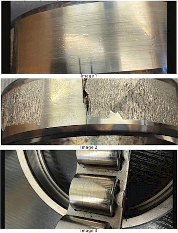
The pictures to the left show the following:
- Image 1: The small pitting visible here are the type of marks that prove that contamination is present.
- Image 2: The heavily pitted area on the inner race shows where the contamination developed deep spalls and began to form a fracture network. This eventually developed into a complete fracture through the part of the outer race.
- Image 3: there for the rollers...
The case study we’ve looked at helps us draw several conclusions.
Early on, we established the importance of designing your maintenance program on a solid foundation of accurate reliability data. We also learned that CM is one of the best tools we can use when striving for effective asset management. Having a timely and accurate understanding of your machine operation and failure modes is the best way to determine the correct combination of activities (PM, CBM, inspection tasks, etc.) that conforms to the apex of the P-F curve and helps us reach a tangible machine life extension.
Above all, we learned that proper training is the single most important investment we can make in our team. Training encourages educated observations and decisions, as well as promotes the culture changes needed to enable your teams’ work in the plant. Training is your plant’s golden parachute, giving you the ability to plan for and manoeuvre around costly failures you used to just endure.
In short, a well-educated, enabled, and organized team with a proper reliability culture will save a lot of unnecessary costs.
