Effective Varnish Removal from Turbine Lubrication Systems
 In recent years, the power-generation industry has seen an increase in varnish-related problems in combustion turbines. This increase is attributed to higher operating temperatures, smaller fluid reservoirs, more peaking and cyclic service, highly refined base stocks that have lower solvency for varnish precursors, and a more widespread use of finer filtration that causes more electrostatic charging of the turbine oil.
The solvency of varnish in turbine oil is temperature dependent, with the transition point being in the range of 130 to 135 degrees F. The temperature frequently falls below this threshold in the hydraulic control section of turbines, resulting in the formation of deposits on control valves.
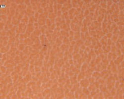 The most problematic aspect of varnish contamination of a turbine lubrication and control system is that the material plates out on servo-valve surfaces, leading to valve sticking, and plugs the last-chance filters (LCFs) that are part of the servo-valve assembly.
LCFs made with sintered metal or fine screens provide a convenient surface for the formation of varnish because of their location in the low-flow, colder hydraulic control section. Lower temperature promotes varnish formation because of the lower solubility of the material at lower temperatures, which causes it to come out of solution and deposit on the filter’s metal surface.
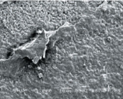 Filters made with glass-fiber media normally are not plugged by varnish. Full-flow filters as fine as 6 microns are known to have no varnish-related premature plugging, although the fluid may have elevated levels of varnish-forming material. The plugging of metal pencil filters but not the larger glass-fiber filters is likely due to the difference in the interaction of the varnish material with metal versus the glass fiber, the cooler temperatures in the hydraulic section and the lower flow velocity.
In addition to the servo-valve deposits, varnish precursors form deposits on mechanical seals, Babbitt sleeve bearings, thrust-bearing pads and orifices, resulting in restrictions. When these deposits develop on heat exchanger and reservoir walls, reduced heat transfer and higher temperatures are likely to occur.
What is Varnish?
Varnish is the thin, insoluble film deposit that forms on fluid-wetted surfaces inside a turbine lube system, including bearings and servo valves. The material is comprised of a wide range of oil additives and high molecular weight thermo-oxidative fluid breakdown compounds that have limited solvency in the base fluid. These compounds are polar in nature and begin to migrate from the base fluid to the wetted surfaces over time, based on the system and fluid conditions and their polar affinities.
This photomicrograph shows varnish
material on an analysis membrane
(0.45-micron porosity) at 100x magnification.
Initially, the surfaces show a gold/tan color, building to darker gum-like layers that eventually develop into a hard, lacquer-like material. The chemical compositions of these insoluble materials vary depending on the turbine operating conditions, the fluid base stock and additive type.
How Varnish Forms
All turbine oils create insoluble materials, even under normal operating conditions. The rate of generation is accelerated under severe or unusual operating conditions. Factors such as oxidation, hot spots, chemical contamination, filter-related electrostatic discharge, micro-dieseling and adiabatic compression are widely believed to be among the sources of varnish generation.
Typical hydrocarbon-based fluids undergo oxidative degradation/polymerization to produce oil-insoluble sludge/varnish. A number of oxygenated chemical compounds can be generated during the course of thermal oxidation, including acids, alcohols, esters, ketones, etc. However, studies have shown that varnish precursors have species that contain predominantly two oxygen atoms per molecule, pointing to the role of hydroxyl-acids as active intermediates in varnish formation.
The chemical species responsible for varnish formation is not always related to the base stock. The additive package and its interaction with the base stock may play a significant role in varnish formation.
Oxidation-inhibitor additives are added to fluids to control the oxidation process. Two common categories of additives are hindered phenols and aromatic amines. Hindered phenols act as radical scavengers. They are more suited for lower temperatures, while amines perform better at higher temperatures.
The mixed phenol/amine additive package has proven to be more robust, as the phenols also rejuvenate the depleted amines. A type of amine antioxidant, PANA, is known to form deposits of its own when it depletes.
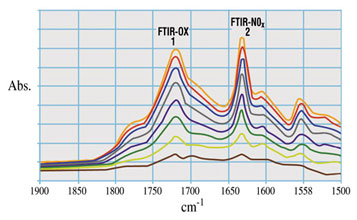 Once the additives are depleted, the oxidation process greatly accelerates. Experts recommend close monitoring of the depletion of phenol and amine antioxidants. When the phenolic antioxidants approach the depletion level, you can expect amine levels to begin falling and the varnish potential to rise.
Elevated temperatures also contribute to the oxidation process. The general rule of thumb is that for every increase of 10 degrees C (18 degrees F) in the operating temperature, the rate of oxidation doubles (Arrhenius rate rule). Water, aeration and wear metal particles such as iron and copper act as catalysts to speed up this process.
Besides oxidation, the other major pathway for fluid degradation in a turbine is thermal degradation. Three common sources of thermal degradation of the fluid and resulting varnish formation are adiabatic compression of the oil-entrained air bubbles, hot spots in the system and filter-induced electrostatic discharge.
The source of air bubbles entrained in fluid can be suction line leaks, pump seal leaks and tank agitation caused by the plunging fluid returning to the reservoir. When exposed to fast compression, such as at the inlet of a high-pressure pump or high-load region of a bearing, these air bubbles can undergo rapid adiabatic compression with a resultant rapid increase in fluid temperatures. Typically, temperatures in the range of 1,000 degrees F may be reached during this adiabatic compression of the air bubbles. The high temperature initiates thermal degradation of the fluid, leading to the formation of varnish.
Electrostatic or tribo-electric charge generation occurs in turbine lubrication systems as a result of friction between the fluid and the system components. The magnitude of the charge generated depends on many interrelated factors, including environmental issues. This effect manifests itself in several ways, with the most noticeable being an audible clicking sound as the accumulated charge discharges. This causes sparking internally within the system. Less apparent effects involve migration of the electrical charge downstream of the filter, which produces damage to system components and the filter.
Recently, attention has been directed to fluid electrification and static discharge as prominent contributors to sludge and varnish formation in turbine systems. The amount of charge generated by the flow of a hydrocarbon liquid through a filter is related to several fluid and filter properties. Charge generation/accumulation generally increases with increasing flow rates (velocity through the filter element), reduced fluid conductivity, certain additive packages and lower temperature (higher viscosity).
In the filter housing, the charge of the filter element will be opposite in sign to that of the fluid. The charge on the fluid will be transmitted downstream, and if enough charge is accumulated, the fluid dielectric constant is exceeded. The discharge then occurs to a conductive part of the filtration or fluid system that is lower in magnitude, resulting in potential damage to that part of the system. The extent of damage will depend on the material involved and the magnitude of the generated charge.
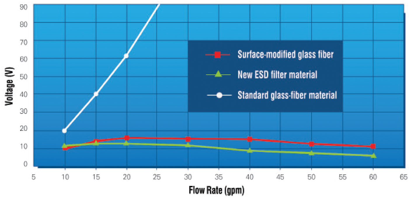
Various methods have been tried to alleviate the potential of static charge accumulation in fluid systems. Among them are anti-static additives, which may not be suitable for turbine oils; the use of conductive mesh downstream of the filter material, which has limited effectiveness in preventing charge accumulation in the fluid; and increasing the time for the charge to decay, which requires a change in the system design. Filtering the fluid at a lower flow density (i.e., increasing the filter size) does rectify the problem, but it is not a viable option for every system. Several manufacturers have introduced filters with filtration media designed not to generate a charge to the same extent as the standard glass-fiber-based materials.
In 2004, a new series of electrostatic dissipative (ESD) filter media were introduced to eliminate potential electrostatic charging problems in filtration of hydrocarbon fluids. Extensive testing in controlled laboratory conditions and on operating equipment in many industrial applications has shown this filtration media to eliminate filter damage and significantly lower charge generation compared with the typical glass-fiber filtration medium.
Varnish Removal Technologies
The currently available solution for removing varnish from turbine lubrication fluids can be divided into three categories - electrostatic purification, chemical cleaning/flushing and adsorption by a disposable media.
The electrostatic method, operating in kidney-loop mode off the main tank, subjects the fluid to an electrical field, which causes the varnish precursors to charge and agglomerate into larger particles that are then captured by a filter mat or attracted to a charged, disposable surface.
There are several designs based on variants of the electrostatic charging principle to accomplish this goal. The electrostatic-type devices are reported to remove varnish precursors from the fluid phase, and as the fluid is cleaned up, soft varnish deposits from surfaces are re-entrained in the fluid and removed, thus resulting in the cleaning up of deposits accumulated over a period of time.
| Turbine | Fluid ID | Initial Varnish Rating | Filtered Varnish Rating |
|---|---|---|---|
| GE Frame 7B* | A | 59 | 0 |
| GE Frame 7FA* | B | 47 | 0 |
| GE Frame 7FA* | B | 47 | 22** |
| GE Frame 7FA | C | 62 | 15*** |
| Alstom GT8C | D | 34 | 11 |
| Alstom GT24B | E | 85 | 15*** |
| MHI 501 (G) | F | 58 | 15*** |
| * Varnish rating determined by Herguth Laboratories. ** Filtered at 160 degrees F. *** The varnish rating of filtrate is estimated. The initial alues are by Analysts Inc. |
|||
Since the removal of varnish from system components is a relatively slow process, these devices are recommended to be operated over a long period of time or to be installed permanently. They are reported to be sensitive to elevated moisture levels in the fluid and also to the presence of high levels of metal wear particles.
The chemical cleaning/flushing method for removing varnish utilizes cleaning chemicals that are typically circulated through the system to dislodge varnish from components. These chemicals soften and dissolve the insoluble materials, and the flushing action suspends the hard deposits in the fluid, which are then removed with the fluid when it is drained from the system. This process is usually performed for several hours or several days, depending on the system size and the extent of the varnish build-up on components.
Once the flush and chemical treatment is completed, the system must be flushed again with an appropriate flushing fluid to remove residual chemicals and to ensure no contamination finds its way into the new lubricating oil. Although this process is more intensive, it does allow for quicker removal of varnish deposits, especially in a large system. It also requires close monitoring and entails lost production due to the turbine being out of operation.
The adsorption method utilizes adsorbent media with a large surface area and high void volume, relatively low fluid flux and in some cases an electro-chemical affinity for varnish precursors. Many materials can be used as adsorbents, including compressed cellulose, cotton linters and macro-porous media such as resin beads, Fuller’s earth, activated carbon, etc.
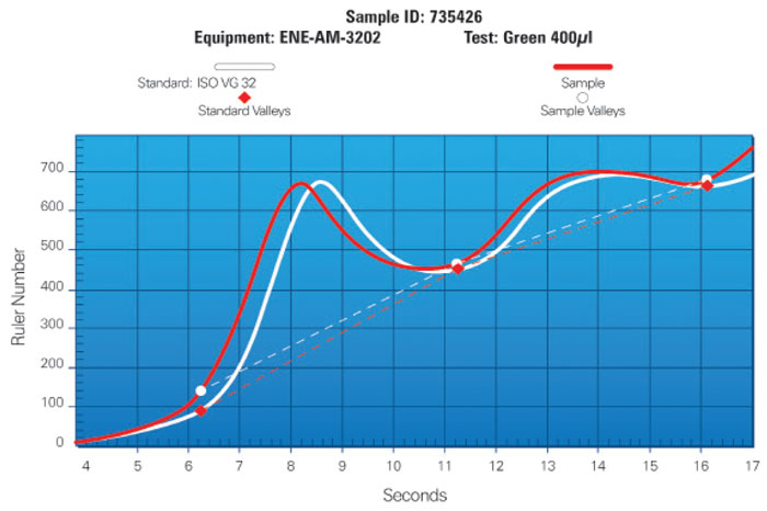
There are two types of adsorption: physisorption and chemisorption. Physisorption, also called physical adsorption, is a process in which the adsorbent material and the adsorbate molecules (varnish precursors) do not form chemical bonds arising from a chemical reaction but are bonded by weak electrostatic forces arising from induced dipole moments such as van der Waals forces. The electronic structure of the adsorbate does not change upon adsorption. Because of its chemical structure, varnish molecules are believed to be attracted to the adsorbent through weak molecular forces such as hydrogen bonding.
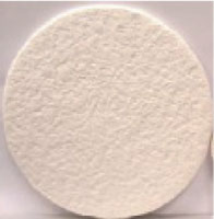
A filtration medium based on physisorption, called a Varnish Removal Filter (VRF), has been developed. This filtration medium is a composite consisting of a cellulose fiber matrix and other materials that give it a high-void volume and an open-fiber matrix. The resin-bonded, open-fiber matrix provides high permeability, which is necessary for the fluid to come in contact with the large fiber surface area for the absorption of the varnish precursors. The specially formulated binder resins give the filter media high affinity for the polar varnish precursors, resulting in high removal efficiency and retention of the material suspended in the fluid phase.
The VRF medium was tested in a laboratory using samples of degraded fluid obtained from operating turbines that had reported high levels of varnish. The values (shown in the table above) were taken after single-pass filtration at ambient room temperature, except for the third test, which was conducted at a fluid temperature of 160 degrees F. The higher varnish rating of the filtrate sample at a higher temperature indicates lower varnish removal performance, likely due to the higher solvency of the varnish precursors in the fluid and lower absorbency at an elevated temperature.
Tests were also conducted to assess the effect on the fluid’s additives as a result of the treatment with the VRF medium. The results indicated essentially no change in the level of aromatic amine and hindered phenol between the unfiltered sample and the sample that was filtered 20 times. The absence of any depletion of this additive suggested that the VRF medium had no noticeable adverse effect on the fluid.
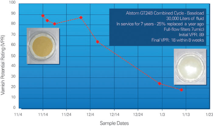
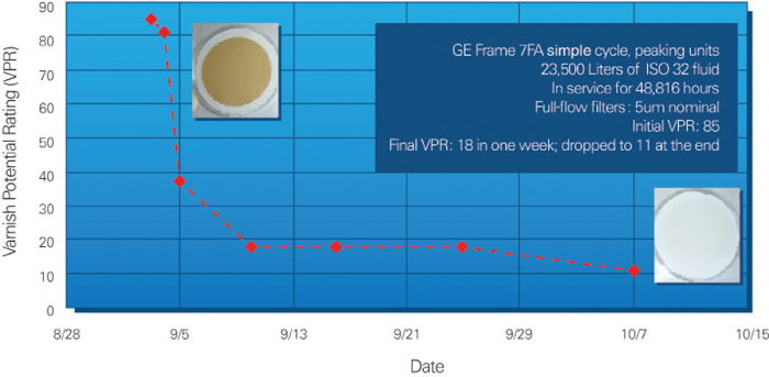
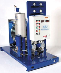 Following successful laboratory validation of the filtration medium, a skid incorporating the VRF filter modules and the associated control system was tested on two operating turbines. The treatment of the turbine lubrication systems entailed installation of the skid in a kidney-loop mode, taking the fluid from one end of the reservoir and returning it to the opposite end continuously. Both trials ran uninterrupted with minimal operator intervention and utilized one set of three VRF modules for each trial. The removal and retention of varnish material by the filtration medium was indicated by the staining of the medium by the varnish material.
One significant difference between the two turbines treated with the VRF was the level of varnish deposits in the lubrication systems. The inside of the main flow filter housing on the Alstom turbine lubrication system indicated the presence of a heavy brownish coating of varnish material. No such deposits were observed in the GE Frame 7FA turbine lubrication system.
 Following clean-up of the Alstom turbine, the VRF skid was removed, and the plant re-installed the electrostatic-type cleaner that had been used before the VRF treatment. A sample from the Alstom turbine was obtained about six months after the VRF treatment and was found to have elevated varnish levels. The GE Frame 7FA turbine was sampled two months after the VRF treatment and had low varnish levels similar to that at the time of the termination of the treatment.
The reason for the recurrence of the high varnish level in the Alstom turbine is believed to be the heavy varnish deposits in the system that were not completely removed during the eight weeks of the fluid treatment, although the varnish precursors in the fluid phase were reduced to very low levels. The difference in the fluid clean-up rate, which was longer in the case of the Alstom turbine, and the slight increase after the initial decrease in the varnish level can also be attributed largely to the presence of heavy varnish deposits in the Alstom turbine lubrication system.
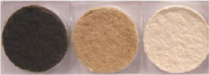 The two field trials revealed that the amount and type of varnish deposits in the lubrication system had a bearing on how quickly the fluid could be rid of the varnish material and for how long after the clean-up it would remain free of elevated varnish levels. There are also variables other than the level of deposits, such as the type of the varnish material, temperature, duty cycle, fluid type, state of the deposits, etc., that influence the rate of varnish removal from the fluid and the dissolution of the deposits back into the fluid.
 In summary, the mitigation of varnish-related problems in turbine lubrication and hydraulic control systems requires not only cleaning up the varnish precursors from the fluid and the soluble deposits from the wetted surfaces, but also controlling their formation. The absorptive filter technology discussed is engineered to remove the polar varnish precursors and has proven to be effective in the removal of the varnish material from turbine lubrication systems.
In addition, filter-induced electrostatic charging can be controlled with the utilization of specially designed, charge-dissipative filtration media that produce much lower fluid charging, thus mitigating the associated fluid damage while providing the fine levels of filtration required by modern turbines.
